4 layers90 × 25 mm

 tenderlove/camera-clicker7
WiFi client and remote shutter for Olympus OM-D cameras
Camera clicker is an open-source printed circuit board by tenderlove, from the tenderlove/camera-clicker repository on GitHub, published under the Apache-2.0 licence. It is a 2-layer board of 28 × 95 mm with 30 parts on 48 nets, routed with 176 tracks and 17 vias.
It is built around the BQ25170DSG and ESP32-MINI-1. Its parts include 10 resistors, 4 capacitors, 4 switches, 2 ICs and 2 diodes. It belongs with the radio and wireless boards and the ESP32 boards of this library.

This project is a dedicated WiFi client and remote shutter for Olympus OM-D cameras. It simply connects to the camera, and then you can use the button to fire the camera shutter. I've only tested this with my OM-D E-M5 Mark III camera, but I believe it will work with any OM-D camera that uses WiFi for its remote shutter application.
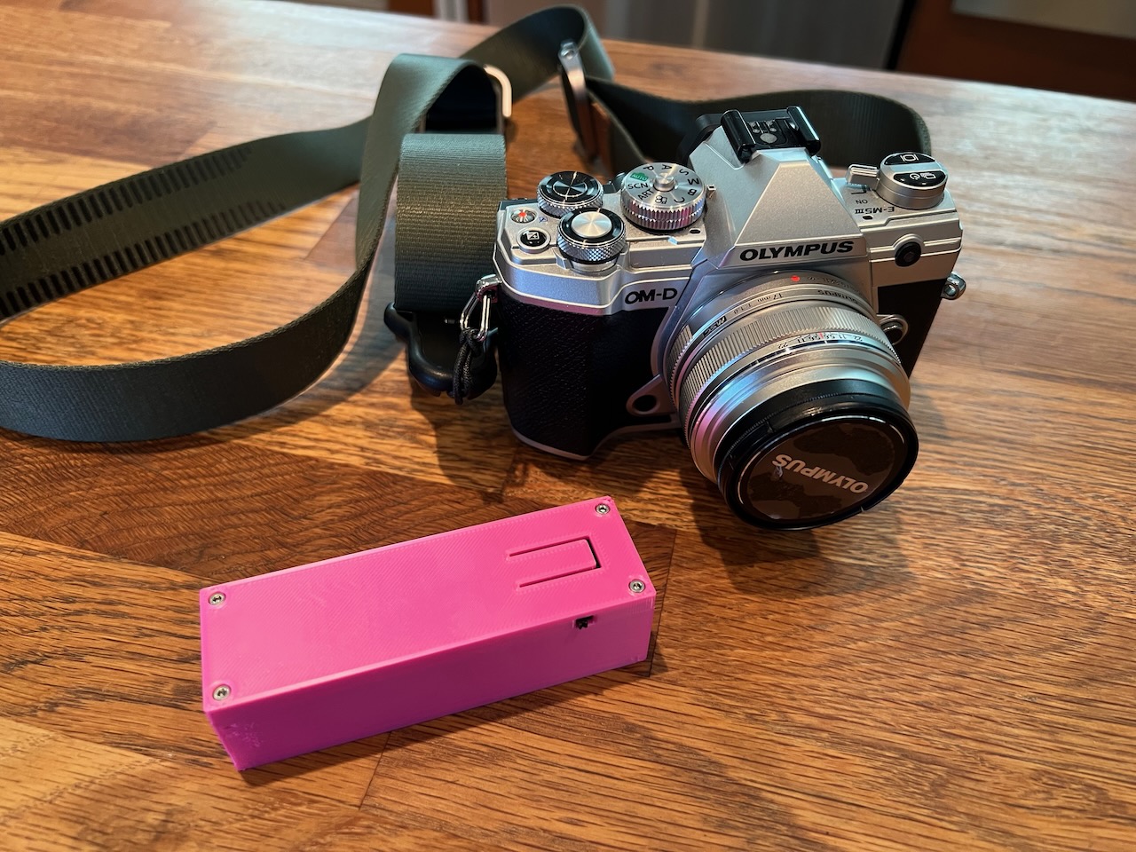
In this repository, you'll find schematics and PCB designs, stl files, and the firmware you need.
The hardware is based around the ESP32. It uses an LiFePO4 battery to provide power to the ESP32. I chose this battery because it provides 3.2v which means I don't need a voltage regulator for the ESP32. The schematic integrates a recharging circuit, so you can recharge the battery via USB C.
Below are the necessary parts:
| Quantity | Part | Value | Size |
|---|---|---|---|
| 1 | Battery Holder | BatteryHolder_Keystone_1042_1x18650 | |
| 1 | Battery | ||
| 2 | Capacitor | 1uf | 0402 |
| 1 | Capacitor | 22uf | 1206 |
| 1 | Capacitor | 0.1uf | 1206 |
| 2 | LED | 1206 | |
| 1 | USB C connector | USB_C_Receptacle_Amphenol_10164359-3A | |
| 1 | Resistor | 82k | 0402 |
| 1 | Resistor | 3k | 0402 |
| 4 | Resistor | 10k | 1206 |
| 1 | Resistor | 70k | 0402 |
| 1 | Resistor | 2.3k | 0402 |
| 2 | Resistor | 5.1k | 1206 |
| 1 | Power Switch | ||
| 2 | Programming Switches | SW_SPST_PTS526 | |
| 1 | Double Action Switch | EVPAX-A1A | |
| 1 | NTC Thermistor | 10k NTC | 1206 |
| 1 | Battery Charger | BQ25170 | WSON-8-1EP_2x2mm_P0.5mm_EP0.9x1.6mm |
| 1 | ESP32 |
You'll find the gerber files in the pcb folder. Also, I used 10k resistors for the LEDs, but I think it made the LEDs too dim, so maybe 1k is better. The LEDs are used to indicate charging status, so I don't think they actually matter too much.
Here's a couple photos of the finished PCB:
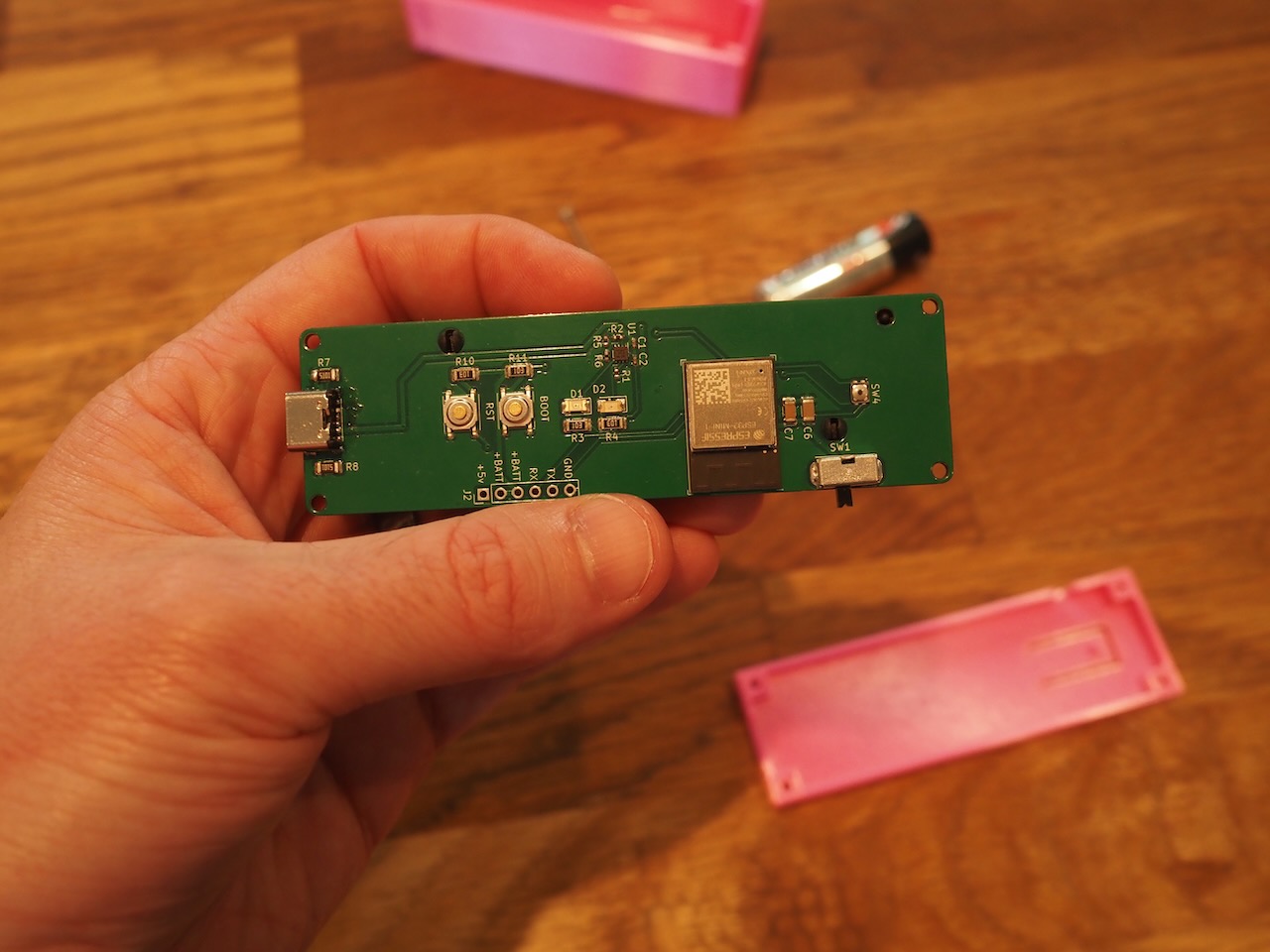
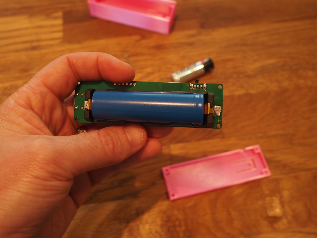
The firmware is in the firmware folder. It's a standard ESP IDF project. In order to flash the ESP32, I used a POGO Pin Clip connected to a USB to Serial board.
Once you have esp-idf installed, you can install the firmware like this:
$ idf.py build flashOf course, make sure to press the BOOT and RST buttons to put the ESP32 in to programming mode.
You can find STL files for the housing in the housing folder.
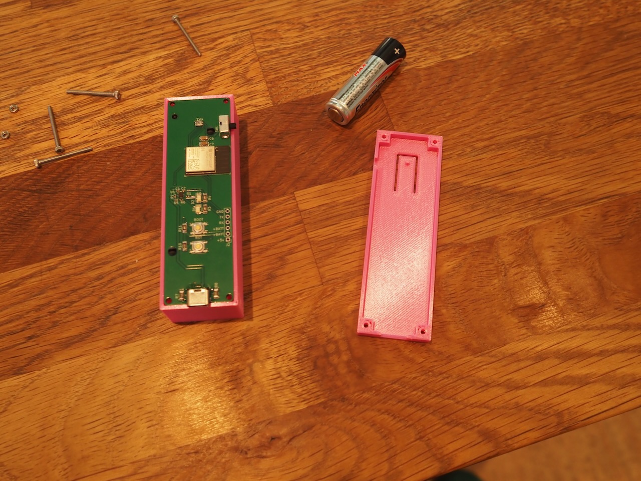
Just print top.stl and bottom.stl and the PCB should fit inside.
The housing requires four M2 x 25mm bolts, and four 4mm hex nuts.
The PCB should fit in the housing like this:
When you first turn the clicker on, it will create a WiFi hotspot with the SSID CameraClicker and the password cameraclicker.
My recommendation is to:
The camera clicker will remember the camera's WiFi connection information, so you only need to configure it once. If it can't connect to the camera for any reason, it will eventually start the WiFi hotspot again so that you can reconfigure it.
| Qty | Value | Footprint | References |
|---|---|---|---|
| 4 | 10k | Resistor_SMD:R_1206_3216Metric | R3, R4, R10, R11 |
| 4 | MountingHole | MountingHole:MountingHole_2.2mm_M2 | H1, H2, H3, H4 |
| 2 | 1uf | Capacitor_SMD:C_0402_1005Metric | C1, C2 |
| 2 | 5.1k | Resistor_SMD:R_1206_3216Metric | R7, R8 |
| 2 | LED | LED_SMD:LED_1206_3216Metric | D1, D2 |
| 1 | 0.1uf | Capacitor_SMD:C_1206_3216Metric | C7 |
| 1 | 10k NTC | Resistor_SMD:R_1206_3216Metric_Pad1.30x1.75mm_HandSolder | TH1 |
| 1 | 2.3k | Resistor_SMD:R_0402_1005Metric | R6 |
| 1 | 22uf | Capacitor_SMD:C_1206_3216Metric | C6 |
| 1 | 3k | Resistor_SMD:R_0402_1005Metric | R2 |
| 1 | 70k | Resistor_SMD:R_0402_1005Metric | R5 |
| 1 | 82k | Resistor_SMD:R_0402_1005Metric | R1 |
| 1 | BOOT | switch-footprints:SW_SPST_PTS526 | SW2 |
| 1 | BQ25170 | Package_SON:WSON-8-1EP_2x2mm_P0.5mm_EP0.9x1.6mm | U1 |
| 1 | Battery | Battery:BatteryHolder_Keystone_1042_1x18650 | BT1 |
| 1 | Conn_01x06 | Connector_PinHeader_2.54mm:PinHeader_1x06_P2.54mm_Vertical | J2 |
| 1 | ESP32-MINI-1 | Espressif:ESP32-MINI-1 | U2 |
| 1 | RST | switch-footprints:SW_SPST_PTS526 | SW3 |
| 1 | SW_DPST_x2 | CameraClickerFootprints:EVPAX-A1A | SW4 |
| 1 | SW_SPST | Button_Switch_THT:SW_CuK_OS102011MA1QN1_SPDT_Angled | SW1 |
| 1 | USB_C_Receptacle_PowerOnly_6P | switch-footprints:USB_C_Receptacle_Amphenol_10164359-3A | J3 |


GhanGhan/SurvBot
Remote controlled robot that surveys the environment it is travelling in


Project-SkyFall/CanSat-2023
This is repository for Czech CanSat team Project SkyFall

It measures 28 × 95 mm and has 2 copper layers, 1.6 mm thick.
30 parts, built around the BQ25170DSG and ESP32-MINI-1. The full list of its parts is on this page, with links to each part's symbol and footprint where PCBKit's library has them.
From the tenderlove/camera-clicker repository on GitHub, at the commit this page was made from: the board is pcb/camera-clicker.kicad_pcb and its schematic pcb/camera-clicker.kicad_sch. PCBKit opens the board in the browser, with nothing to install.
Its repository publishes it under the Apache-2.0 licence: you may reuse it on that licence's terms (keep the author's notice, and for a copyleft licence share your changes alike).