
4 layers160 × 78.8 mm
Remote Controller
GhanGhan/SurvBot
Remote controlled robot that surveys the environment it is travelling in
85 parts
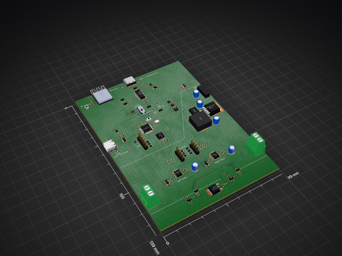
Remote controlled robot that surveys the environment it is travelling in
RCU is an open-source printed circuit board by GhanGhan, from the GhanGhan/SurvBot repository on GitHub. It is a 4-layer board of 99 × 139 mm with 148 parts on 172 nets, routed with 1,056 tracks and 1,375 vias.
It is built around the STM32G0B1CBT6, CH340C and AP63203WU, with the APDS-9306-065, DRV8876PWP and LM2576S-ADJ among its other parts. Its parts include 55 capacitors, 35 resistors, 21 ICs, 17 diodes and 8 connectors. It belongs with the robots and motor control boards and the ESP32 and STM32 boards of this library.


Remote controlled robot that surveys the environment it is travelling in. Designed in KiCad and Altium Designer.
Figure 1: Altium Designer 3D View
Figure 2: KiCad 3D View
Figure 3: SYSTEM BLOCK DIAGRAM (SIMPLE)
Figure 4: SYSTEM OVERVIEW
Figure 5: Power Schematic
Figure 6: Microconroller Schematic
Figure 7: Motor Control Schematic
Figure 8: Bluetooth Schematic
Figure 9: Sensors Schematic
Figure 10: Current Feedback Schematic
Figure 11: External Memory Schematic
Figure 12: 3D View
Battery powered hand-held device that controls and monitors the state of the SurvBot. Commands are sent and data is received over Bluetooth. The design includes joysticks to control the robot’s velocity, buttons to change the mode it is in and a screen to display the sensor data. Can be used outdoors or indoors.
Figure 13: Remote controller Bloack Diagram
The user interface will contain joysticks and buttons to control the robot’s velocity and the state it is in. Such states will determine whether the robot responds to velocity inputs, recording sensor data, is in low power mode etc. Velocity commands and state changes are sent from the controller to the robot via Bluetooth. The controller will receive sensor data; encoders, temperature, humidity and motor current from the robot in and display it on the onboard screen in real time.
The system will:
Figure 14: Power Schematic
Figure 7: Microconroller Schematic
Figure 7: User Interface: Screen, Buttons, and Joysticks
| Qty | Value | Footprint | References |
|---|---|---|---|
| 16 | 0.1uF | Capacitor_SMD:C_0603_1608Metric | C300, C302, C303, C305, C307, C308, C401, C402, C403, C405, C409, C501, C502, C504, C604, C609 |
| 10 | PESD3V3L1BA,115 | Diode_SMD:D_SOD-323 | D200, D201, D202, D203, D300, D301, D302, D303, D304, D305 |
| 7 | 0.1uF | Capacitor_SMD:C_0402_1005Metric | C201, C203, C206, C600, C602, C605, C607 |
| 7 | 1uF | Capacitor_SMD:C_0603_1608Metric | C107, C108, C111, C112, C406, C500, C700 |
| 5 | 10k | Resistor_SMD:R_0603_1608Metric | R402, R403, R404, R405, R500 |
| 5 | 22uF | Capacitor_SMD:C_0603_1608Metric | C105, C106, C109, C110, C404 |
| 4 | 10k | Resistor_SMD:R_0402_1005Metric | R201, R202, R300, R306 |
| 4 | 20k | Resistor_SMD:R_0603_1608Metric | R302, R303, R308, R309 |
| 4 | 40k | Resistor_SMD:R_0603_1608Metric | R304, R305, R310, R311 |
| 4 | 5.1k | Resistor_SMD:R_0603_1608Metric | R205, R206, R400, R401 |
| 4 | OPA320 | Package_TO_SOT_SMD:SOT-23-5 | U300, U302, U601, U603 |
| 4 | SM5817 | Schottky_Diode:SODFL3719X135N | D101, D102, D103, D104 |
| 3 | 2N7002NXAKR (NMOS) | Package_TO_SOT_SMD:SOT-23 | Q400, Q401, Q403 |
| 2 | 1.6k | Resistor_SMD:R_0603_1608Metric | R601, R603 |
| 2 | 10uF | Capacitor_SMD:C_0402_1005Metric | C601, C606 |
| 2 | 10uF | Capacitor_SMD:C_0603_1608Metric | C103, C400 |
| 2 | 14pF | Capacitor_SMD:C_0402_1005Metric | C204, C205 |
| 2 | 15R | Resistor_SMD:R_0402_1005Metric | R600, R607 |
| 2 | 1nF | Capacitor_SMD:C_0402_1005Metric | C603, C608 |
| 2 | 2.2k | Resistor_SMD:R_0603_1608Metric | R301, R307 |
| 2 | 220uF | Capacitor_THT:CP_Radial_D5.0mm_P2.50mm | C301, C306 |
| 2 | 22nF | Capacitor_SMD:C_0603_1608Metric | C304, C309 |
| 2 | 3.9uH | Inductor_SMD:L_0402_1005Metric | L102, L103 |
| 2 | 49R9 | Resistor_SMD:R_0603_1608Metric | R207, R208 |
| 2 | ADC121C027CIMK/NOPB | Package_TO_SOT_SMD:TSOT-23-6 | U600, U602 |
| 2 | SW_Push | Button_Switch_SMD:SW_SPST_B3U-1000P | SW201, SW400 |
| 2 | USBLC6-2SC6 | Package_TO_SOT_SMD:SOT-23-6 | U201, U400 |
| 2 | USB_C_Receptacle_USB2.0 | Connector_USB:USB_C_Receptacle_HRO_TYPE-C-31-M-12 | J200, J400 |
| 1 | 0.1u | Capacitor_SMD:C_0603_1608Metric | C408 |
| 1 | 0R | Resistor_SMD:R_0402_1005Metric | R200 |
| 1 | 1.5k | Resistor_SMD:R_0603_1608Metric | R101 |
| 1 | 1000uF | Capacitor_THT:CP_Radial_D5.0mm_P2.50mm | C102 |
| 1 | 100nF | Capacitor_SMD:C_0603_1608Metric | C104 |
| 1 | 100uF | Capacitor_THT:CP_Radial_D5.0mm_P2.50mm | C101 |
| 1 | 110R | Resistor_SMD:R_0603_1608Metric | R407 |
| 1 | 15uH | Inductor_SMD:L_0603_1608Metric | L101 |
| 1 | 16MHz | Crystal:Crystal_SMD_3225-4Pin_3.2x2.5mm | Y200 |
| 1 | 1u | Capacitor_SMD:C_0603_1608Metric | C407 |
| 1 | 1uF | Capacitor_SMD:C_0402_1005Metric | C200 |
| 1 | 4.7uF | Capacitor_SMD:C_0402_1005Metric | C202 |
| 1 | 40R | Resistor_SMD:R_0603_1608Metric | R406 |
| 1 | 470u | Capacitor_THT:CP_Radial_D5.0mm_P2.50mm | C100 |
| 1 | 5R | Resistor_SMD:R_0603_1608Metric | R102 |
| 1 | 68uH | 68uH Power Inductor:IND_MWSA1206S_SNL | L100 |
| 1 | 8.9k | Resistor_SMD:R_0603_1608Metric | R100 |
| 1 | AP63203WU | Package_TO_SOT_SMD:TSOT-23-6 | U101 |
| 1 | APDS-9306-065 | OptoDevice:Broadcom_DFN-6_2x2mm_P0.65mm | U500 |
| 1 | AZ1117-3.3 | Package_TO_SOT_SMD:TO-252-2 | U102 |
| 1 | B340 | Diode_SMD:D_SMC | D100 |
| 1 | BSS84AK,215 (PMOS) | Package_TO_SOT_SMD:SOT-23 | Q402 |
| 1 | Blue LED | LED_SMD:LED_0603_1608Metric | D406 |
| 1 | CH340C | Package_SO:SOP-16_3.9x9.9mm_P1.27mm | U401 |
| 1 | Conn_01x02 | Connector_Wire:SolderWire-2sqmm_1x02_P7.8mm_D2mm_OD3.9mm | J100 |
| 1 | Conn_01x05 | Connector_PinHeader_2.54mm:PinHeader_1x05_P2.54mm_Vertical | J201 |
| 1 | DG2788ADN-T1-GE4 | UQFN-16(1.8x2.6):QFN40P260X180X55-16N | U403 |
| 1 | DRV8876 | Package_SO:HTSSOP-16-1EP_4.4x5mm_P0.65mm_EP3.4x5mm_Mask2.46x2.31mm | U301 |
| 1 | DRV8876 | Package_SO:HTSSOP-16-1EP_4.4x5mm_P0.65mm_EP3.4x5mm | U303 |
| 1 | ESP32-MINI-1 | ESP32_MINI:XCVR_ESP32-MINI-1-N4 | U402 |
| 1 | Green LED | LED_SMD:LED_0603_1608Metric | D405 |
| 1 | LM2576S-ADJ | Package_TO_SOT_SMD:TO-263-5_TabPin3 | U100 |
| 1 | LSM6DS3 | Package_LGA:LGA-14_3x2.5mm_P0.5mm_LayoutBorder3x4y | U501 |
| 1 | Left_Encoder_Conn | Connector_PinHeader_2.54mm:PinHeader_1x04_P2.54mm_Vertical | J303 |
| 1 | Left_Motor_Screw_Terminal | TerminalBlock:TerminalBlock_bornier-2_P5.08mm | J302 |
| 1 | Right_Encoder_Conn | Connector_PinHeader_2.54mm:PinHeader_1x04_P2.54mm_Vertical | J301 |
| 1 | Right_Motor_Screw_Terminal | TerminalBlock:TerminalBlock_bornier-2_P5.08mm | J300 |
| 1 | SHT30-DIS | Sensor_Humidity:Sensirion_DFN-8-1EP_2.5x2.5mm_P0.5mm_EP1.1x1.7mm | U502 |
| 1 | SST26VF032BT-104I/SM | Package_SO:SOIC-8_5.275x5.275mm_P1.27mm | U700 |
| 1 | STM32G0B1CBT6 | Package_QFP:LQFP-48_7x7mm_P0.5mm | U200 |
| 1 | SW_SPDT | SPDT_JS102011JCQN:SW_JS102011JCQN | SW401 |
GhanGhan/SurvBot
Remote controlled robot that surveys the environment it is travelling in


Protocentral/healthypi-move-hw
Hardware files for the HealthyPi Move


lusher00/Robust-IO
Rugged industrial I/O board in KiCad — ATmega1284P, CAN, isolated I/O, high-side switches, and motor drivers. Schematic complete, PCB routing in progress.

adeboni/laser-projector
This project is for a quadruple laser projection controller, aimed at supporting room-scale projections

KimotoHoitsu/Voiture-guidee-par-main
Ce projet consiste à développer une voiture télécommandée via un contrôleur personnalisé utilisant la communication Bluetooth Low Energy (BLE) et un accéléromètre ADXL.


r-map/rmap
rete monitoraggio ambientale partecipativo documentation at https://doc.rmap.cc
It measures 99 × 139 mm and has 4 copper layers, 1.61 mm thick.
148 parts, built around the STM32G0B1CBT6, CH340C, AP63203WU and APDS-9306-065. The full list of its parts is on this page, with links to each part's symbol and footprint where PCBKit's library has them.
From the GhanGhan/SurvBot repository on GitHub, at the commit this page was made from: the board is PCBs/KiCad/RCU/RCU.kicad_pcb and its schematic PCBs/KiCad/RCU/ADCs.kicad_sch. PCBKit opens the board in the browser, with nothing to install.
Its repository states no licence, so its author keeps all rights: ask GhanGhan before reusing the design.