


4 layers159.1 × 101.4 mm
Robust io.before sw2
lusher00/Robust-IO
Rugged industrial I/O board in KiCad — ATmega1284P, CAN, isolated I/O, high-side switches, and motor drivers. Schematic complete, PCB routing in progress.
258 parts

 lusher00/Robust-IO
Rugged industrial I/O board in KiCad — ATmega1284P, CAN, isolated I/O, high-side switches, and motor drivers. Schematic complete, PCB routing in progress.
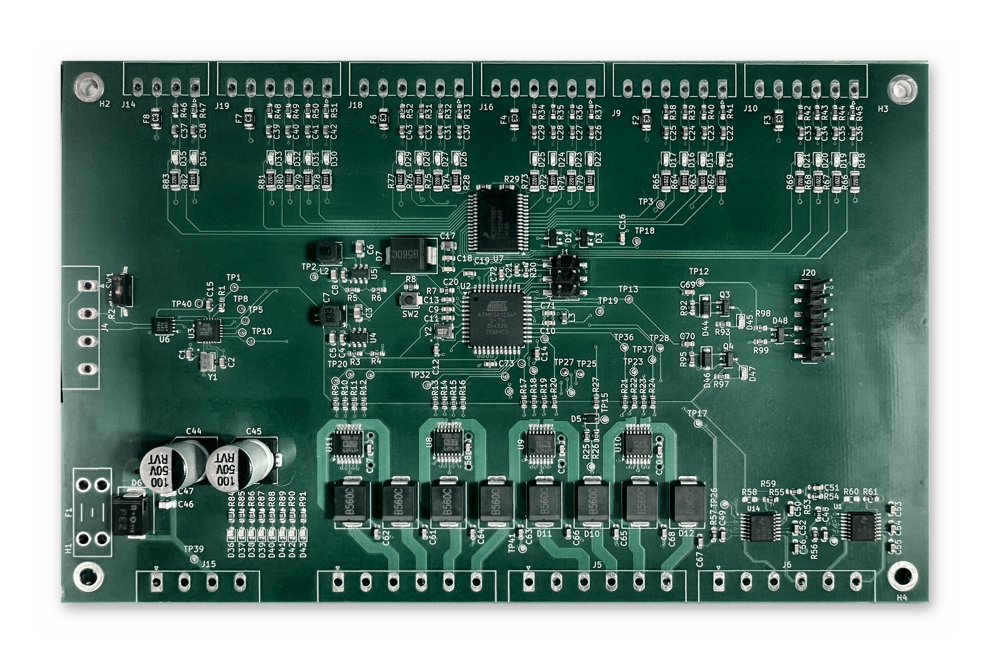
Robust io is an open-source printed circuit board by lusher00, from the lusher00/Robust-IO repository on GitHub. It is a 4-layer board of 160 × 100 mm with 304 parts on 205 nets, routed with 1,992 tracks and 343 vias.
It is built around the ATMEGA1284P-AU, DRV8876PWP and B560C, with the 1N4148W, BAT54C and B340 among its other parts. Its parts include 97 resistors, 73 capacitors, 46 diodes, 11 connectors and 9 ICs. It belongs with the robots and motor control boards and the AVR (ATmega, ATtiny) boards of this library.


A rugged industrial I/O board designed in KiCad 10.
| Item | Value |
|---|---|
| Size | 160 x 100 mm, four M3 mounting holes |
| Layers | 4: F.Cu signal, In1 GND plane, In2 +24V plane, B.Cu signal |
| Copper | 2 oz outer, 1 oz inner |
| Minimum drill | 0.3 mm |
| Supply | 24 V nominal through a blade fuse (F1) and SMDJ24A TVS |
| Assembly | SMD parts on top side only; through-hole connectors and fuse holder hand-fitted |
| Sheet | Contents |
|---|---|
power | Two TPS560430 buck regulators (+5V, +3.3V), input fuse, TVS, bulk capacitors |
processor | ATmega1284P, MCP2515 + MCP2562 (CAN), crystals, ISP header (J1), UART header (J20), reset button |
inputs | MC33978 22-channel switch detect with fused, filtered inputs and status LEDs |
outputs2 | Four BTS7008-2EPA dual high-side switches (8 outputs), two DRV8876 motor drivers |
41 test points (35 top, 6 bottom) cover the supply rails, SPI, UART, CAN
interrupt, driver control and sense lines, and ground. Positions and nets are
listed in fab/robust-io-testpoints.csv.
Supply polarity is not marked on the board. J15 pins 1 and 2 (the square pad end, nearest F1) are +24V; pins 3 and 4 are GND. There is no reverse-polarity protection, so a reversed supply forward-biases D6 and the substrate diodes of every part on the rail. Both rev A boards were powered reversed during bring-up; see the Bring-up log.
MC33978 input LEDs read "input at ground". Each input LED sits between +24V (2.2k) and the IC pin, so it lights when the input is pulled low. That is correct for switch-to-ground sensing, which is all rev A supports; switch-to-battery on an SP channel needs that channel's LED removed, because the 2.2k sources more current than the IC can sink.
BTS7008 GND pins have no series resistor. The datasheet calls for 47 ohm in the GND pin (RGND) and limits GND pin current to 50 mA.
CS_CAN has no pull-up. With the MCU in reset (during ISP) the MCP2515 can drive MISO; programming is unreliable unless the board is power-cycled first. Fit 10k from TP8 to TP1 if it keeps failing.
UART activity LEDs load the lines. C69/C70 (10 nF) with the 1k series resistors give a 10 us edge, too slow for 115200 baud. The console runs at 38400 on rev A.
C57 to C60 use a polarized symbol in the schematic; the fitted parts are 50 V MLCCs and have no polarity.
The BTS7008-2EPA is rated for a 28 V maximum supply. Use a regulated 24 V supply; do not connect directly to a charging battery system.
Reverse polarity protection is the fuse and TVS only. There is no series reverse-blocking stage.
The input polyfuses are rated 30 V, which is a small margin over 24 V.
Y1 load capacitors (22 pF) have not been matched to the crystal's specified load capacitance.
Regulator output tracks are 0.2 mm wide.
MC33978 check frames line in the banner) is the
next step: 0xFFFFFFFF means the chip never drives MISO, 0x00000000 means
it is selected but not shifting.pinctrl set 25 ip pu (or raspi-gpio set 25 ip pu) after programming,
or unplug J1 pin 5, before expecting the board to run./dev/ttyS0) is unreliable for the console even at
38400. Use an FTDI cable on J20 for the console and the Pi only for
programming, or switch the Pi to the PL011 (dtoverlay=disable-bt).fab/revA/ and docs/revA/ before any rev B
output is generated.robust-io.kicad_pro - project filerobust-io.kicad_sch - root sheetpower.kicad_sch, processor.kicad_sch, inputs.kicad_sch, outputs2.kicad_sch - schematic sheetsrobust-io.kicad_pcb - PCB layoutrobust-io.kicad_sym, sym-lib-table - project symbol libraryrobust-io.kicad_dru - custom design rulesDRC.rpt, ERC.rpt - latest check reportsdocs/)| File | Content |
|---|---|
| robust-io-schematic.pdf | Schematic, all sheets |
| layout-top.pdf, layout-bottom.pdf | Copper and silkscreen per side |
| assembly-top.pdf | Assembly drawing with reference designators |
| board-top.png, board-bottom.png, board-angle.png | 3D renders |
| robust-io-revA-top.jpg, robust-io-revA-top-board-only.jpg | Photos of the assembled rev A board (composite of several exposures, rectified to the board outline) |
Regenerate with bash docs/make_docs.sh after saving the schematic and board.
firmware/)ATmega1284P firmware 0.3: UART service console (38400 8N1), CAN protocol with
host timeout, output current trip, motor control, EEPROM settings and a
self-test. Runs on rev A hardware; the MC33978 driver is unverified until the
chip answers (see Bring-up log). Build with make in firmware/ (avr-gcc); make fuses and
make flash program the board from a Raspberry Pi wired to J1. See
firmware/DESIGN.md for the pin map, console commands,
CAN frame layouts and settings.
tools/)Everything for talking to the board over CAN from a Pi, laptop or robot:
a DBC file, a Python package with the robustio command-line tool, a terminal
dashboard, a browser dashboard, a bring-up and end-of-line test runner that
writes a report per board, and a ROS 2 driver node. All of them also run
against the firmware simulator, so they can be used before hardware exists.
See tools/README.md.
fab/)| File | Purpose |
|---|---|
make_gerbers.sh | Plots Gerbers, drill files and the position file with kicad-cli, then zips the Gerbers |
gerbers/, robust-io-gerbers.zip | Gerber and Excellon drill files |
robust-io-BOM-JLC-smd.csv | JLCPCB assembly BOM, 50 lines, LCSC part number on every line |
robust-io-CPL-JLC.csv | JLCPCB placement file |
cpl_rotation_offsets.json | Per-part rotation corrections applied to the placement file |
kicad-pos.csv | Raw KiCad position export |
robust-io-BOM-tht.csv | Through-hole parts to fit by hand (fuse holder, terminal headers) |
robust-io-testpoints.csv | Test point list with nets and positions |
robust-io-fab-all.zip | Everything above in one archive |
To regenerate the Gerbers after a board change, save the board in KiCad and run:
bash fab/make_gerbers.shThe placement file is not produced by the script. JLCPCB's rotation
convention differs from KiCad's for some packages, so the rotation for each
part in robust-io-CPL-JLC.csv is the KiCad rotation plus the offset in
cpl_rotation_offsets.json. Regenerate it whenever parts move, and check
the result in JLCPCB's placement preview before ordering.
firmware/DESIGN.md section 4) and run
make fuses, then make flash, in firmware/. Do this before connecting
any load to J3 or J5: until the fuses disable JTAG, outputs 2 to 5 can
switch on by themselves. Release the reset line afterward
(pinctrl set 25 ip pu).ver, then selftest.robustio bringup --console /dev/serial0 --serial <n>
from tools/, which writes a report for the board.robustio bringup --loads once all are connected).See LICENSE. Free for personal, educational, and open-source use. For commercial licensing, contact ryan.lush@gmail.com.
| Qty | Value | Footprint | References |
|---|---|---|---|
| 33 | .1uF | Capacitor_SMD:C_0603_1608Metric | C10, C13, C14, C15, C18, C20, C21, C22, C23, C24, C25, C26, C27, C28, C29, C30 +17 |
| 32 | LED | LED_SMD:LED_0603_1608Metric | D14, D15, D16, D17, D18, D19, D20, D21, D22, D23, D24, D25, D26, D27, D28, D29 +16 |
| 22 | 100 | Resistor_SMD:R_0603_1608Metric_Pad0.98x0.95mm_HandSolder | R31, R32, R33, R34, R35, R36, R37, R38, R39, R40, R41, R42, R43, R44, R45, R46 +6 |
| 22 | 2.2k | Resistor_SMD:R_1206_3216Metric | R62, R63, R64, R65, R66, R67, R68, R69, R70, R71, R72, R73, R74, R75, R76, R77 +6 |
| 17 | .1uF | Capacitor_SMD:C_0603_1608Metric_Pad1.08x0.95mm_HandSolder | C4, C48, C49, C51, C57, C58, C59, C60, C61, C62, C63, C64, C65, C66, C67, C68 +1 |
| 17 | 4.7k | Resistor_SMD:R_0603_1608Metric | R10, R11, R12, R13, R14, R15, R16, R17, R18, R19, R20, R21, R22, R23, R24, R26 +1 |
| 13 | 10k | Resistor_SMD:R_0603_1608Metric_Pad0.98x0.95mm_HandSolder | R1, R7, R28, R29, R53, R84, R85, R86, R87, R88, R89, R90, R91 |
| 8 | B560C | Diode_SMD:D_SMC | D2, D4, D8, D9, D10, D11, D12, D13 |
| 6 | Polyfuse | Fuse:Fuse_1206_3216Metric | F2, F3, F4, F6, F7, F8 |
| 5 | Screw_Terminal_01x06 | Connector_Phoenix_MC:PhoenixContact_MC_1,5_6-G-3.5_1x06_P3.50mm_Horizontal | J9, J10, J16, J18, J19 |
| 4 | 22pF | Capacitor_SMD:C_0603_1608Metric | C1, C2, C11, C12 |
| 4 | BTS7008 | Package_SO:TSSOP-14-1EP_4.4x5mm_P0.65mm | U8, U9, U10, U11 |
| 4 | GND | TestPoint:TestPoint_Pad_D1.0mm | TP38, TP39, TP40, TP41 |
| 4 | MountingHole_Pad | MountingHole:MountingHole_3.2mm_M3_DIN965_Pad_TopBottom | H1, H2, H3, H4 |
| 3 | 330 | Resistor_SMD:R_0603_1608Metric_Pad0.98x0.95mm_HandSolder | R8, R93, R97 |
| 3 | Screw_Terminal_01x06 | Connector_Phoenix_MSTB:PhoenixContact_MSTBA_2,5_6-G-5,08_1x06_P5.08mm_Horizontal | J3, J5, J6 |
| 2 | 0 | Resistor_SMD:R_0603_1608Metric_Pad0.98x0.95mm_HandSolder | R59, R61 |
| 2 | 1.5k 1% | Resistor_SMD:R_0603_1608Metric_Pad0.98x0.95mm_HandSolder | R56, R57 |
| 2 | 100k | Resistor_SMD:R_0603_1608Metric_Pad0.98x0.95mm_HandSolder | R92, R95 |
| 2 | 100nF 16V | Capacitor_SMD:C_0603_1608Metric_Pad1.08x0.95mm_HandSolder | C52, C54 |
| 2 | 100nF 50V | Capacitor_SMD:C_0603_1608Metric_Pad1.08x0.95mm_HandSolder | C55, C56 |
| 2 | 100uF 50V | Capacitor_SMD:CP_Elec_8x10 | C44, C45 |
| 2 | 10nF | Capacitor_SMD:C_0603_1608Metric | C69, C70 |
| 2 | 1N4148W | Diode_SMD:D_SOD-123 | D44, D46 |
| 2 | 1k | Resistor_SMD:R_0603_1608Metric | R98, R99 |
| 2 | 2.2uF | Capacitor_SMD:C_0805_2012Metric_Pad1.18x1.45mm_HandSolder | C3, C6 |
| 2 | 22.1k | Resistor_SMD:R_0603_1608Metric_Pad0.98x0.95mm_HandSolder | R4, R6 |
| 2 | 22nF | Capacitor_SMD:C_0603_1608Metric_Pad1.08x0.95mm_HandSolder | C50, C53 |
| 2 | 22uF | Capacitor_SMD:C_0603_1608Metric_Pad1.08x0.95mm_HandSolder | C5, C8 |
| 2 | 2N7002 | Package_TO_SOT_SMD:SOT-23 | Q3, Q4 |
| 2 | BAT54C | Package_TO_SOT_SMD:SOT-23 | D1, D3 |
| 2 | DRV8876 | rml:IC_DRV8876PWPR | U1, U14 |
| 2 | NP | Resistor_SMD:R_0603_1608Metric_Pad0.98x0.95mm_HandSolder | R58, R60 |
| 2 | Screw_Terminal_01x04 | Connector_Phoenix_MSTB:PhoenixContact_MSTBA_2,5_4-G-5,08_1x04_P5.08mm_Horizontal | J4, J15 |
| 2 | TPS5604 | Package_TO_SOT_SMD:SOT-23-6 | U4, U5 |
| 1 | +24V | TestPoint:TestPoint_Pad_D1.0mm | TP3 |
| 1 | +3.3V | TestPoint:TestPoint_Pad_D1.0mm | TP1 |
| 1 | +5V | TestPoint:TestPoint_Pad_D1.0mm | TP2 |
| 1 | .1uF 50V | Capacitor_SMD:C_0805_2012Metric_Pad1.18x1.45mm_HandSolder | C47 |
| 1 | 10-20A | Fuse:Fuseholder_Blade_Mini_Keystone_3568 | F1 |
| 1 | 10k 1% | Resistor_SMD:R_0603_1608Metric_Pad0.98x0.95mm_HandSolder | R55 |
| 1 | 10uF 50V | Capacitor_SMD:C_0805_2012Metric | C17 |
| 1 | 10uH | Capacitor_SMD:C_0603_1608Metric | L3 |
| 1 | 120 | Resistor_SMD:R_0603_1608Metric_Pad0.98x0.95mm_HandSolder | R2 |
| 1 | 12MHz | rml:WE-XTAL_CFPX-180 | Y2 |
| 1 | 16.2k 1% | Resistor_SMD:R_0603_1608Metric_Pad0.98x0.95mm_HandSolder | R54 |
| 1 | 16MHz | rml:WE-XTAL_CFPX-180 | Y1 |
| 1 | 18uH | Inductor_SMD:L_Sunlord_SWPA4030S | L2 |
| 1 | 1k | Resistor_SMD:R_0603_1608Metric_Pad0.98x0.95mm_HandSolder | R30 |
| 1 | 1n | Capacitor_SMD:C_0603_1608Metric | C19 |
| 1 | 1nF | Capacitor_SMD:C_0603_1608Metric | C16 |
| 1 | 2.2uF 50V | Capacitor_SMD:C_0805_2012Metric_Pad1.18x1.45mm_HandSolder | C46 |
| 1 | 4.7k | Resistor_SMD:R_0603_1608Metric_Pad0.98x0.95mm_HandSolder | R27 |
| 1 | 51k | Resistor_SMD:R_0603_1608Metric_Pad0.98x0.95mm_HandSolder | R3 |
| 1 | 6.8uH | Inductor_SMD:L_Sunlord_SWPA4030S | L1 |
| 1 | 750 | Resistor_SMD:R_0603_1608Metric | R25 |
| 1 | 88.7k | Resistor_SMD:R_0603_1608Metric_Pad0.98x0.95mm_HandSolder | R5 |
| 1 | AMUX0 | TestPoint:TestPoint_Pad_D1.0mm | TP16 |
| 1 | ATmega1284P-A | Package_QFP:TQFP-44_10x10mm_P0.8mm | U2 |
| 1 | AVR-ISP-6 | Connector_PinHeader_2.54mm:PinHeader_2x03_P2.54mm_Vertical_SMD | J1 |
| 1 | B340 | Diode_SMD:D_SMC | D7 |
| 1 | B3U-1000P | Button_Switch_SMD:SW_SPST_B3U-1000P | SW2 |
| 1 | BZX384C6V8 | Diode_SMD:D_SOD-323 | D5 |
| 1 | CHS-01TB | Button_Switch_SMD:SW_DIP_SPSTx01_Slide_Copal_CHS-01B_W7.62mm_P1.27mm | SW1 |
| 1 | CS_CAN | TestPoint:TestPoint_Pad_D1.0mm | TP8 |
| 1 | CS_IN0 | TestPoint:TestPoint_Pad_D1.0mm | TP7 |
| 1 | DEN0 | TestPoint:TestPoint_Pad_D1.0mm | TP20 |
| 1 | DEN1 | TestPoint:TestPoint_Pad_D1.0mm | TP21 |
| 1 | DEN2 | TestPoint:TestPoint_Pad_D1.0mm | TP22 |
| 1 | DEN3 | TestPoint:TestPoint_Pad_D1.0mm | TP23 |
| 1 | DRV_OUT0 | TestPoint:TestPoint_Pad_D1.0mm | TP30 |
| 1 | DRV_OUT1 | TestPoint:TestPoint_Pad_D1.0mm | TP31 |
| 1 | DRV_OUT2 | TestPoint:TestPoint_Pad_D1.0mm | TP32 |
| 1 | DRV_OUT3 | TestPoint:TestPoint_Pad_D1.0mm | TP33 |
| 1 | DRV_OUT4 | TestPoint:TestPoint_Pad_D1.0mm | TP34 |
| 1 | DRV_OUT5 | TestPoint:TestPoint_Pad_D1.0mm | TP35 |
| 1 | DRV_OUT6 | TestPoint:TestPoint_Pad_D1.0mm | TP36 |
| 1 | DRV_OUT7 | TestPoint:TestPoint_Pad_D1.0mm | TP37 |
| 1 | DSELn | TestPoint:TestPoint_Pad_D1.0mm | TP19 |
| 1 | EN_M0 | TestPoint:TestPoint_Pad_D1.0mm | TP24 |
The 280 most common of 304 parts.
lusher00/Robust-IO
Rugged industrial I/O board in KiCad — ATmega1284P, CAN, isolated I/O, high-side switches, and motor drivers. Schematic complete, PCB routing in progress.


GhanGhan/SurvBot
Remote controlled robot that surveys the environment it is travelling in

gallicchio/AMOD-and-RFMOD
The tutorial's 2x12 adapter (/mudd/133electronics/icepi-zero-dac-adc/adapterboard/) with a 2 x 6 right-angle Pmod socket on a 15 mm extension of its right-hand end, so an Icepi Zero can drive AMOD-A's and RF-MOD's Pmod…

fkontiebo/flight-controller
Contrôleur de vol 4 layers basé sur STM32F405RGT6, conçu comme plateforme de navigation autonome avec bus CAN.

brown-studios/minuet
Minuet upgrades your MAXXAIR Maxxfan with a brushless DC motor, home automation features, and accessories.


It measures 160 × 100 mm and has 4 copper layers, 1.6 mm thick.
304 parts, built around the ATMEGA1284P-AU, DRV8876PWP, B560C and 1N4148W. The full list of its parts is on this page, with links to each part's symbol and footprint where PCBKit's library has them.
From the lusher00/Robust-IO repository on GitHub, at the commit this page was made from: the board is robust-io.kicad_pcb and its schematic _claude_scratch/inputs.before-erc.kicad_sch. PCBKit opens the board in the browser, with nothing to install.
Its repository states no licence, so its author keeps all rights: ask lusher00 before reusing the design.