2 layers84.5 × 84.5 mm
 teletype7/IRIS3
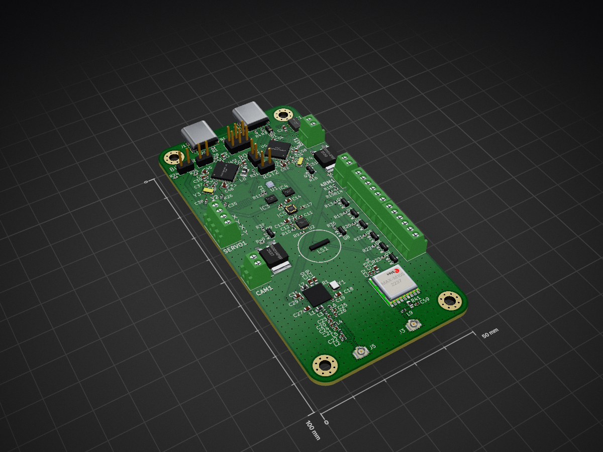
StDevboard is an open-source printed circuit board by teletype7, from the teletype7/IRIS repository on GitHub, published under the MIT licence. It is a 4-layer board of 50 × 100 mm with 166 parts on 179 nets, routed with 1,715 tracks and 888 vias.
It is built around the MPM3610GQV-Z, AT25SF041B-SSHB-B and BMP581, with the MMC5983MA, ICM-45686 and IRFR9014PBF among its other parts. Its parts include 59 capacitors, 46 resistors, 12 ICs, 9 transistors and 9 inductors. It belongs with the STM32 boards of this library.


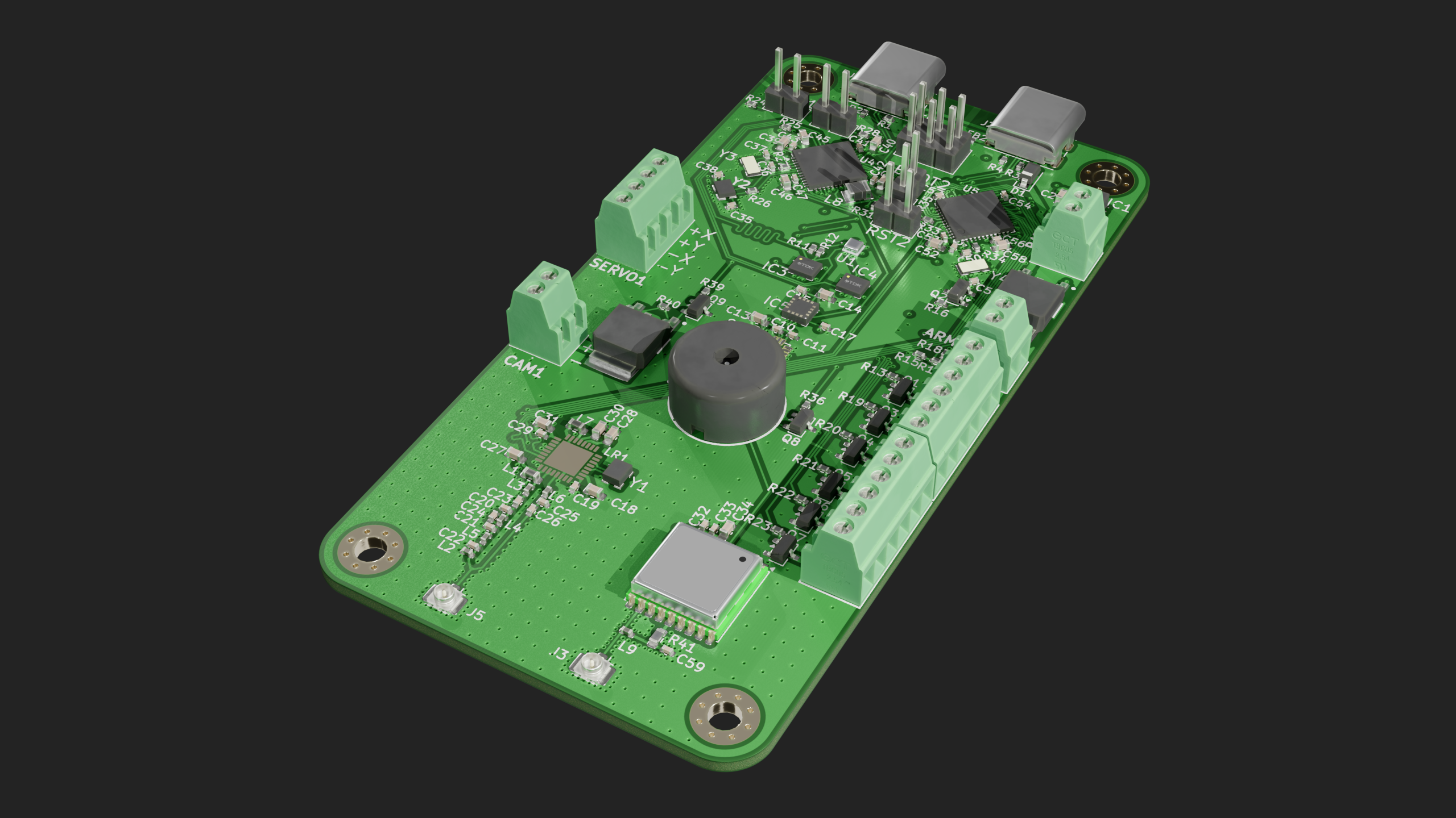
IRIS is an advanced flight computer designed for controlling guided model rockets. It is specifiacally designed for aerodynamic control, but is also capable of thrust vector control.
IRIS has 6 pyrotechnic channels with a shared arming circuit. The continuity of each channel may be individually sensed. Each pyro channel may be independently controlled. There is also a physical arming switch for safety.
It has 4 servo output channels, on the main microcontroller's dedicated pwm output pins so they incur no extra cpu load.
It has a controlled output camera power header, to lower power draw while idling on the pad or waiting for recovery.
There is a UART broken out from each microcontroller for debugging purposes, just in case the USB doesn't work.
Finally, IRIS has a high performance lora transceiver onboard for long range telemetry, ensuring that even the highest flights may be safely flown and recovered.
IRIS has 2 high performance imus, one for lower range higher precision sensing, and one for higher range lower precision sensing. By having dedicated imus for each range, IRIS can maintain a high precision across the entire flight envelope.
IRIS also includes an ultra high g accelerometer (which will not be populated on the prototype boards for cost reasons), a high performance high sensitivity magnetometer, and an ultra high sensitivity barometer. There is additionally a GPS for stable position updates.
By fusing all of its sensors IRIS can create an accurate vehicle position esitmate across a wide range of flight profiles. This position estimate may then be used in GNC (Guidance, Navigation, and Control) algorithms to control the flight of a vehicle.
IRIS uses 2 microcontrollers, one main processor and one auxilary processor. By using this architecture, one fast processor with lots of ram (the STM32U585 in this case) can handle all of the complex GNC logic that needs super consistent loop times to work. The main processor is in charge of all flight logic and servo control, as well as the sensors. However, we need to also be able to handle very inconsistent actions like telemetry and datalogging. To do that, we use the auxilary processor (the STM32U073 in this case). The auxilary processor is in charge of the pyrotechnic channels (not controlling them, basically just acting as an I/O expander), as well as datalogging to both flash and micro sd, plus sending telemetry.
IRIS switches both the high and low side of the pyro channels, which is entirely about safety - that way there can be a device level digital and physical arm. You can never be too safe with pyrotechnics.
IRIS uses a very comprehensive suite of sensors, including some quite high quality ones. This is to ensure that at least one sensor of each type is never out of range, which would lead to the position estimate being off, thus the GNC going out of control. I don't think I need to say this, but an out of control rocket is not a good thing.
Everything that I chose was chosen for safety or so that IRIS could actually fulfil its intended purpose.
I'm working on designing a rocket with some of my friends, and I needed a flight computer for it, one capable of stabilization.
The testing firmware can be installed with platformio, board configs are in firmware/processor/FC_PROCESSOR. Install those configs then flash with platformio.
This project was made for blueprint, an event ran by Hack Club. Hack Club is a global nonprofit that runs events like this, where teenagers learn valuable skills, like hardware design and programming. You can learn more about my project on the blueprint site, at my project page.
No more firmware development will be done on this repository, we don't want to take the risk of ITAR applying here.
The 22uf decoupling cap for the battery has too low of a voltage rating and should instead be populated with one of the 10uf ones.
The wrong footprint was used for one of the inductors on the lr2021, it should be 0402.
The oscillator loading caps may need to be changed depending on what parasitic capacitance you assume, these are for roughly 4pf parasitic.
The lr2021 implementation is severlely screwed up
tldr don't use this, but take a look at v2 on my github (still in development as of the time of writing)
| Mouser Cart | Digikey Cart | LCSC Cart |
| $89.52 | $51.34 | $38.44 |
| Component Total | ||
| $179.30 | ||
| JLC Cart | ||
| $42.85 | note: not included in above table | |
| Final Total | ||
| $222.15 |
| Qty | Value | Footprint | References |
|---|---|---|---|
| 24 | 100nF | Capacitor_SMD:C_0402_1005Metric | C4, C5, C10, C11, C12, C15, C17, C29, C32, C33, C41, C42, C43, C47, C49, C53 +8 |
| 15 | 10k | Resistor_SMD:R_0402_1005Metric | R17, R24, R25, R28, R31, R32, R33, R35, R37, R38, R40, R42, R43, R44, R45 |
| 12 | 1k | Resistor_SMD:R_0402_1005Metric | R13, R16, R19, R20, R21, R22, R23, R26, R27, R34, R36, R39 |
| 7 | 10uF | Capacitor_SMD:C_0603_1608Metric | C3, C13, C16, C34, C40, C48, C52 |
| 6 | 1uF | Capacitor_SMD:C_0603_1608Metric | C14, C27, C28, C39, C46, C58 |
| 6 | DMN3404L | Package_TO_SOT_SMD:SOT-23 | Q1, Q3, Q4, Q5, Q6, Q7 |
| 4 | 2.2uF | Capacitor_SMD:C_0603_1608Metric | C18, C30, C44, C45 |
| 4 | 2.7k | Resistor_SMD:R_0402_1005Metric | R9, R10, R11, R12 |
| 4 | 5.1K | Resistor_SMD:R_0402_1005Metric | R1, R2, R3, R4 |
| 4 | 9pF | Capacitor_SMD:C_0402_1005Metric | C36, C37, C50, C51 |
| 4 | Conn_01x02 | Connector_PinHeader_2.54mm:PinHeader_1x02_P2.54mm_Vertical | BOOT1, BOOT2, RST1, RST2 |
| 3 | 100k | Resistor_SMD:R_0402_1005Metric | R8, R18, R32 |
| 3 | BLM15AX102SN1D | footprints:NFZ15SG152SN10B | FB1, FB2, FB3 |
| 3 | MMBT2222A | Package_TO_SOT_SMD:SOT-23 | Q2, Q8, Q9 |
| 2 | 1.8pF | Capacitor_SMD:C_0402_1005Metric | C22, C24 |
| 2 | 12k | Resistor_SMD:R_0402_1005Metric | R14, R29 |
| 2 | 22uF | Capacitor_SMD:C_0603_1608Metric | C1, C2 |
| 2 | 3k | Resistor_SMD:R_0402_1005Metric | R15, R30 |
| 2 | 8pF | Capacitor_SMD:C_0402_1005Metric | C35, C38 |
| 2 | CM7V-T1A-32.768KHZ | footprints:CM7V32768TBQA020 | Y3, Y4 |
| 2 | Conn_Coaxial | Connector_Coaxial:U.FL_Hirose_U.FL-R-SMT-1_Vertical | J3, J5 |
| 2 | ICM-45686 | footprints:ICM42670P | IC3, IC4 |
| 2 | IRFR9014PBF | footprints:TO228P990X238-3N | IC2, IC7 |
| 2 | Screw_Terminal_01x06 | footprints:TBC05061GG | PYRO1, PYRO2 |
| 2 | USB_C_Receptacle_USB2.0_16P | Connector_USB:USB_C_Receptacle_GCT_USB4085 | J1, J2 |
| 1 | 10 | Resistor_SMD:R_0603_1608Metric | R41 |
| 1 | 10nF | Capacitor_SMD:C_0402_1005Metric | C59 |
| 1 | 12nH | Inductor_SMD:L_0603_1608Metric | L1 |
| 1 | 18pF | Capacitor_SMD:C_0402_1005Metric | C26 |
| 1 | 2.2 uH, 1.5A | footprints:INDC2520X120N | L8 |
| 1 | 2.2pF | Capacitor_SMD:C_0402_1005Metric | C25 |
| 1 | 2.2uH | Inductor_SMD:L_0603_1608Metric | L7 |
| 1 | 22nH | Inductor_SMD:L_0402_1005Metric | L2 |
| 1 | 22pF | Capacitor_SMD:C_0402_1005Metric | C23 |
| 1 | 24k | Resistor_SMD:R_0402_1005Metric | R6 |
| 1 | 24nH | Inductor_SMD:L_0402_1005Metric | L6 |
| 1 | 27nH | Inductor_SMD:L_0402_1005Metric | L9 |
| 1 | 3.9nH | Inductor_SMD:L_0402_1005Metric | L4 |
| 1 | 3.9pF | Capacitor_SMD:C_0402_1005Metric | C21 |
| 1 | 39k | Resistor_SMD:R_0402_1005Metric | R7 |
| 1 | 4.7nH | Inductor_SMD:L_0402_1005Metric | L3 |
| 1 | 4.7uF | Capacitor_SMD:C_0603_1608Metric | C31 |
| 1 | 47pF | Capacitor_SMD:C_0402_1005Metric | C19 |
| 1 | 7.5nH | Inductor_SMD:L_0402_1005Metric | L5 |
| 1 | 7.5pF | Capacitor_SMD:C_0402_1005Metric | C20 |
| 1 | 75k | Resistor_SMD:R_0402_1005Metric | R5 |
| 1 | AT25SF041B-SSHB-B | footprints:SOIC127P600X175-8N | IC6 |
| 1 | Arm | footprints:TBC05021GG | ARM1 |
| 1 | BMP581 | footprints:BMP581 | U1 |
| 1 | Conn_01x04 | footprints:TBC05041GG | SERVO1 |
| 1 | Conn_02x03_Top_Bottom | Connector_PinHeader_2.54mm:PinHeader_2x03_P2.54mm_Vertical | DEBUG1 |
| 1 | D_Schottky | Diode_SMD:D_SOD-123 | D1 |
| 1 | ECS-160-8-36B2-CKM-TR | footprints:ECS160836B2CKMTR | Y2 |
| 1 | ECS-TXO-25CSMV-320-AM-TR | footprints:ECSTXO25CSMV320AMTR | Y1 |
| 1 | H3LIS331DLTR | footprints:QFN300X300X100-16N | U2 |
| 1 | LOGO | footprints:logo | G*** |
| 1 | MAX-M10S | RF_GPS:ublox_MAX | U3 |
| 1 | MMC5983MA | footprints:MMC5983MA | IC5 |
| 1 | MPM3610GQV-Z | footprints:MPM3606GQVZ | IC1 |
| 1 | Micro_SD_Card_Det2 | Connector_Card:microSD_HC_Molex_104031-0811 | J10 |
| 1 | PS1240P02BT | footprints:PS1240P02BT | LS1 |
| 1 | STM32U073CCUx | Package_DFN_QFN:QFN-48-1EP_7x7mm_P0.5mm_EP5.6x5.6mm | U5 |
| 1 | STM32U585CIUxQ | Package_DFN_QFN:QFN-48-1EP_7x7mm_P0.5mm_EP5.6x5.6mm | U4 |
| 1 | Screw_Terminal_01x02 | footprints:TBC05021GG | CAM1 |
| 1 | battery | footprints:TBC05021GG | BAT1 |
| 1 | ~ | footprints:LR2021 | LR1 |
The 162 most common of 166 parts.
It measures 50 × 100 mm and has 4 copper layers, 1.6 mm thick.
166 parts, built around the MPM3610GQV-Z, AT25SF041B-SSHB-B, BMP581 and MMC5983MA. The full list of its parts is on this page, with links to each part's symbol and footprint where PCBKit's library has them.
From the teletype7/IRIS repository on GitHub, at the commit this page was made from: the board is pcb/stDevboard.kicad_pcb and its schematic pcb/mosfets.kicad_sch. PCBKit opens the board in the browser, with nothing to install.
Its repository publishes it under the MIT licence: you may reuse it on that licence's terms (keep the author's notice, and for a copyleft licence share your changes alike).

NCSU-High-Powered-Rocketry-Club/FIRM-KiCad
Full and open hardware design for FIRM


xDocka15/GNSS_geret
Dokument popisuje zmeny/upravy v elektronike gnss-geret z 2024 tak aby vznikla jednodoskova prenostitelna verzia.


tenderlove/initial-v
It's a BMW shifter converted to a Bluetooth Keyboard that you use with Vim

