Skip to the content
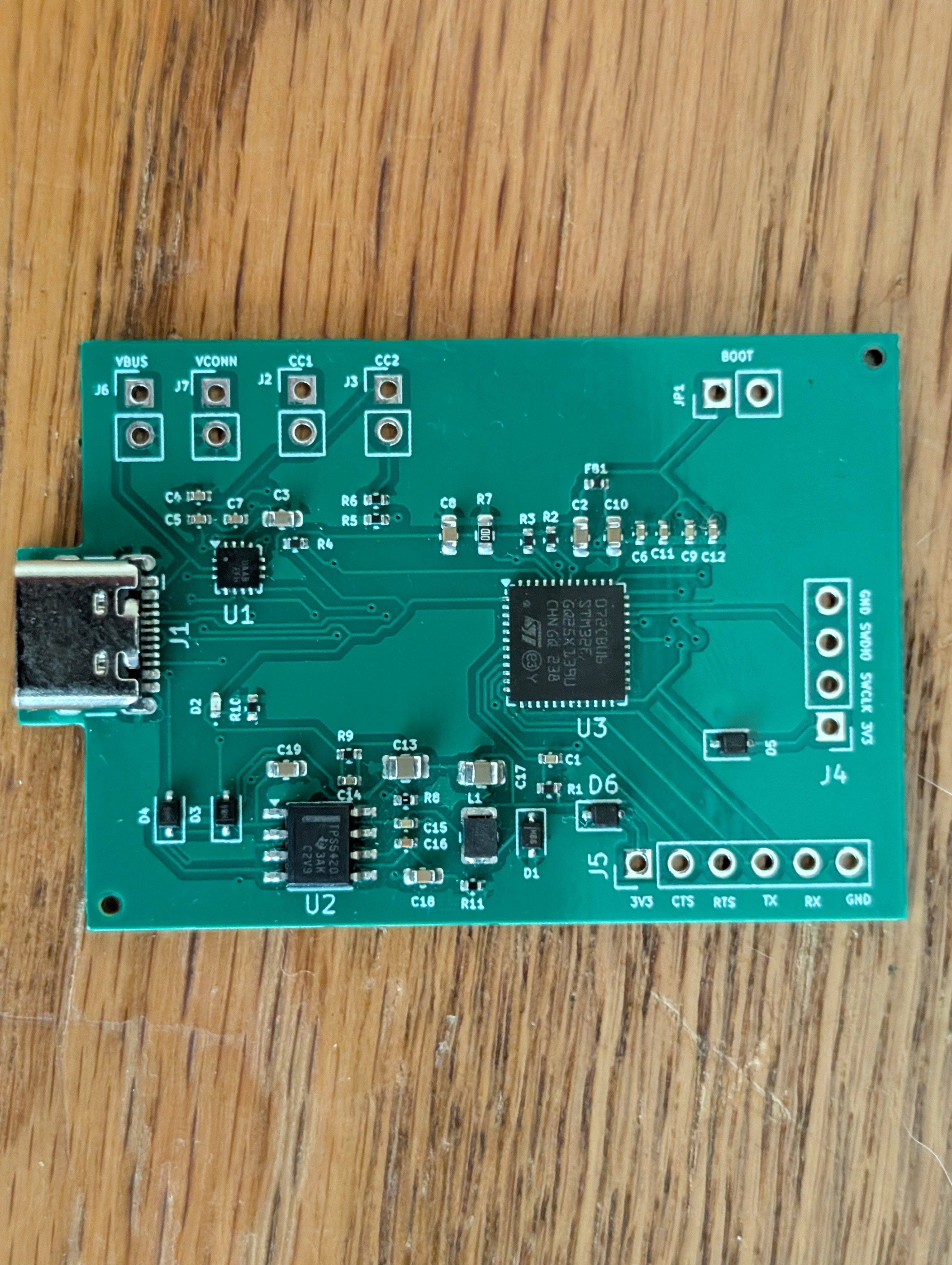
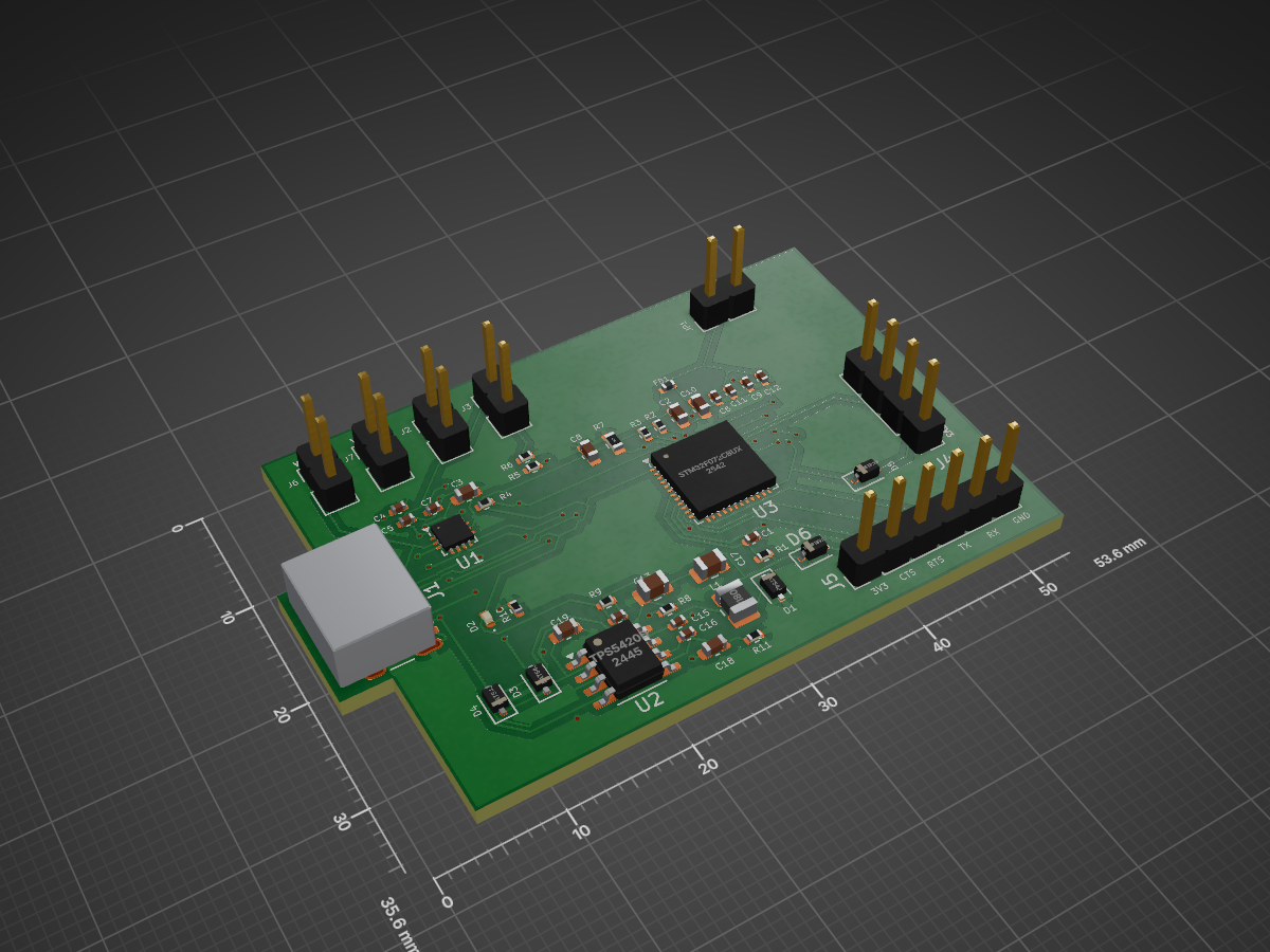
2 layers53.6 × 35.6 mmPd board, the printed circuit board in 3D

The PD Logger firmware logs PD messages, attach/dettach events, CC voltage/orientation, and VBUS voltage. Connect to the board through UART and use a serial terminal to interact with the FUSB302 over I2C via the…

Size
53.6 × 35.6 mm
Copper layers
2
Thickness
1.6 mm
Parts
49
Nets
61
Pads
210
Tracks, vias
536, 40
Pours
5
Routed
Yes
KiCad
KiCad 9.0 (file 20241229)
Created
30 Dec 2025
Updated
20 Feb 2026

Overview

Pd board is an open-source printed circuit board by teleplayer123, from the teleplayer123/PD_Logger repository on GitHub, published under the MIT licence. It is a 2-layer board of 53.6 × 35.6 mm with 49 parts on 61 nets, routed with 536 tracks and 40 vias.

It is built around the FUSB302BMPX, TPS5420D and BAT54J, with the 1N5819WS among its other parts. Its parts include 19 capacitors, 11 resistors, 7 connectors, 6 diodes and 3 ICs. It belongs with the STM32 boards of this library.

Main components

4

README

README.md

Description

A development board to experiment with USB-C PD via an STM32 and FUSB302.

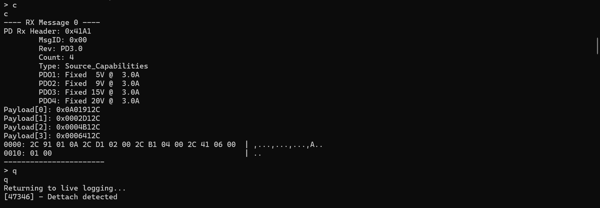
The PD Logger firmware logs PD messages, attach/dettach events, CC voltage/orientation, and VBUS voltage. Connect to the board through UART and use a serial terminal to interact with the FUSB302 over I2C via the STM32F0. Logs will start showing once a PD capable device is detected. A debug console menu can be accessed by pressing Enter in the terminal allowing direct writes and reads to the FUSB302. Press "q" to exit the debug console and return to live logging. A python script to communicate with the PD Logger over a serial port is included in the firmware folder.

Dev Board
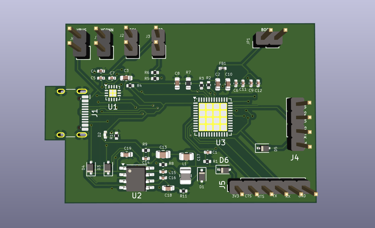
DevBoardPreview

DevBoard

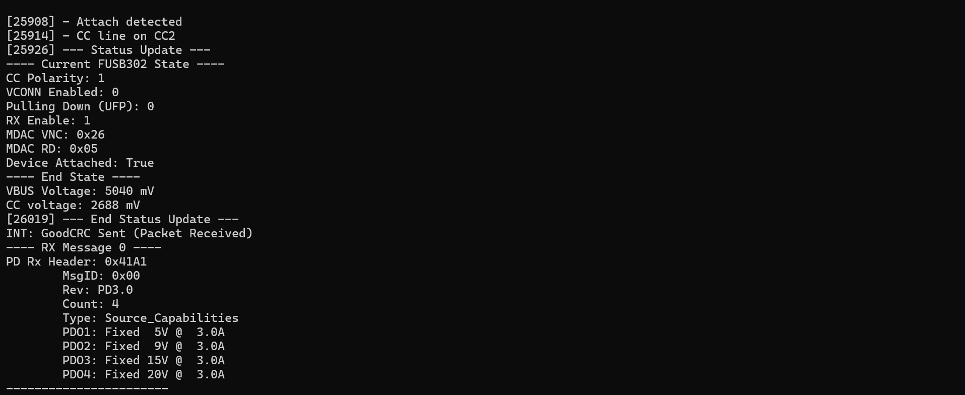
Example: Attach & Dettach Charger

Attaching USB-C PD charger: ChargerAttach
Enter debug menu (charger still attached): DebugMenu

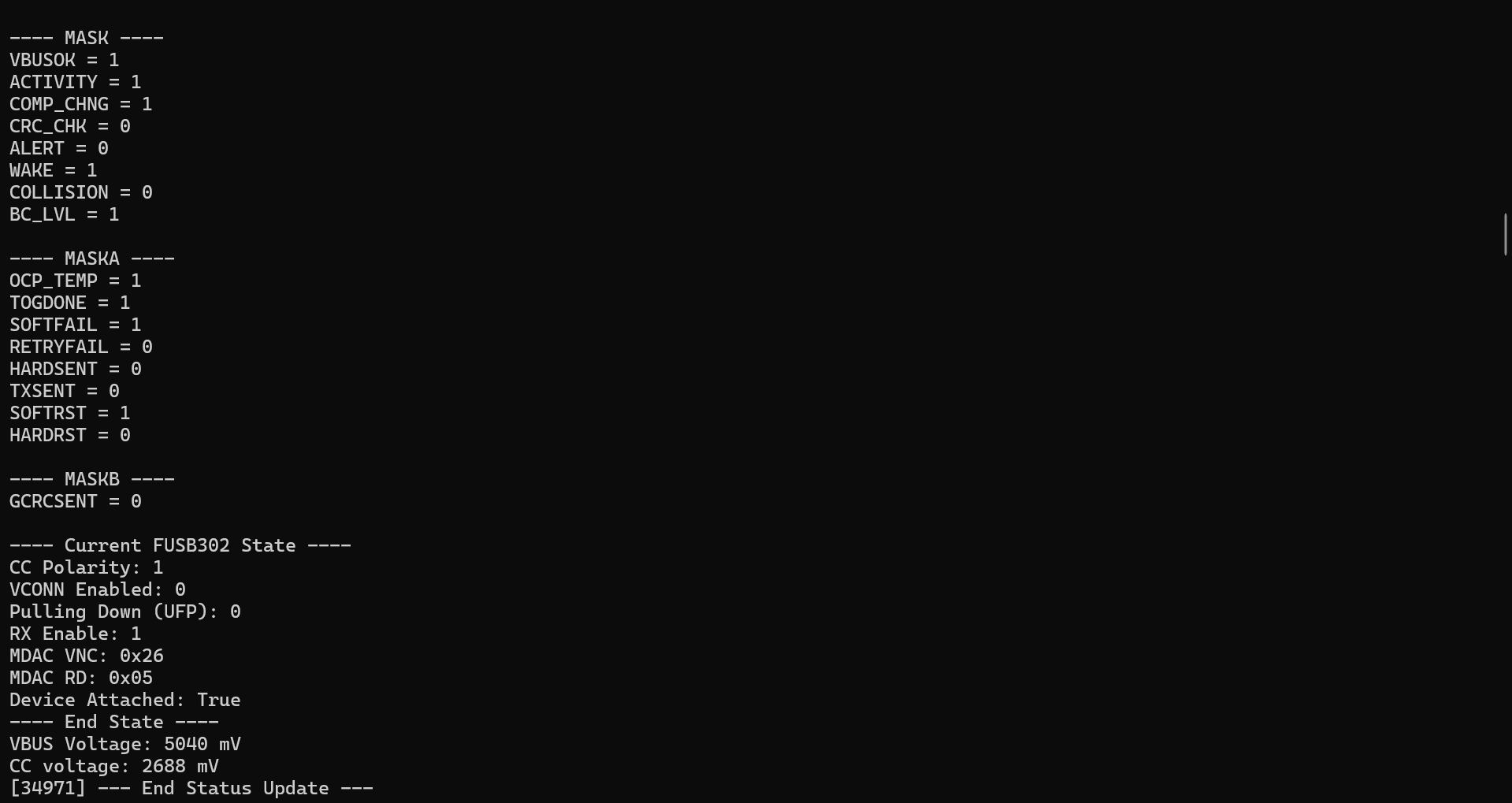
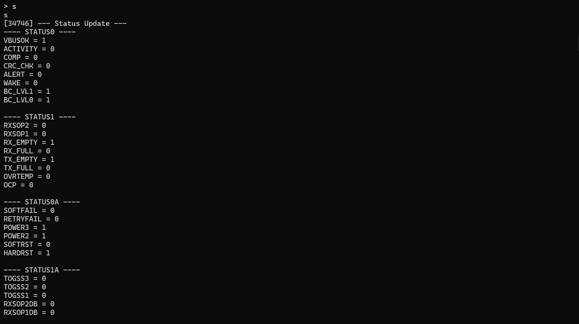
Viewing FUSB302B status registers and state machine status: CheckStatusStart CheckStatusEnd
View saved PD messages and quiting debug console, followed by dettaching the charger: DumpMsgQuitDettach
Resources

Thanks to these projects for helping me learn about USB-C PD and utilizing the FUSB302!

USB-C-Explorer

AltmodeFriend
Parts

49
QtyValueFootprintReferences
3100nFCapacitor_SMD:C_0402_1005MetricC6, C11, C12
34.7kResistor_SMD:R_0402_1005MetricR2, R3, R4
34.7uFCapacitor_SMD:C_0603_1608MetricC2, C8, C19
3BAT54JDiode_SMD:D_SOD-323FD1, D3, D4
210kResistor_SMD:R_0402_1005MetricR1, R9
210nFCapacitor_SMD:C_0402_1005MetricC1, C9
21N5819WSDiode_SMD:D_SOD-323D5, D6
2200pFCapacitor_SMD:C_0402_1005MetricC5, C7
247uFCapacitor_SMD:C_0805_2012MetricC13, C17
25.1kResistor_SMD:R_0402_1005MetricR5, R6
10.01uFCapacitor_SMD:C_0402_1005MetricC15
10.1uFCapacitor_SMD:C_0402_1005MetricC4
10.1uFCapacitor_SMD:C_0603_1608MetricC18
1100kResistor_SMD:R_0603_1608MetricR7
110uFCapacitor_SMD:C_0603_1608MetricC3
1150pFCapacitor_SMD:C_0402_1005MetricC16
11800pFCapacitor_SMD:C_0402_1005MetricC14
118uHInductor_SMD:L_1008_2520MetricL1
11kResistor_SMD:R_0402_1005MetricR10
11uFCapacitor_SMD:C_0603_1608MetricC10
15.9kResistor_SMD:R_0402_1005MetricR11
1549RResistor_SMD:R_0402_1005MetricR8
1600RInductor_SMD:L_0402_1005MetricFB1
1Boot_JumperConnector_PinHeader_2.54mm:PinHeader_1x02_P2.54mm_VerticalJP1
1Dead_Battery_CC1Connector_PinHeader_2.54mm:PinHeader_1x02_P2.54mm_VerticalJ2
1Dead_Battery_CC2Connector_PinHeader_2.54mm:PinHeader_1x02_P2.54mm_VerticalJ3
1Debug PortConnector_PinHeader_2.54mm:PinHeader_1x04_P2.54mm_VerticalJ4
1FUSB302BMPXPackage_DFN_QFN:WQFN-14-1EP_2.5x2.5mm_P0.5mm_EP1.45x1.45mmU1
1PWR_LEDLED_SMD:LED_0402_1005MetricD2
1STM32F072CBUxPackage_DFN_QFN:QFN-48-1EP_7x7mm_P0.5mm_EP5.6x5.6mmU3
1TPS5420DPackage_SO:SOIC-8_3.9x4.9mm_P1.27mmU2
1UART_PortConnector_PinHeader_2.54mm:PinHeader_1x06_P2.54mm_VerticalJ5
1USB_C_Receptacle_USB2.0_16PConnector_USB:USB_C_Receptacle_HCTL_HC-TYPE-C-16P-01AJ1
1VBUS_JPConnector_PinHeader_2.54mm:PinHeader_1x02_P2.54mm_VerticalJ6
1VCONN_JPConnector_PinHeader_2.54mm:PinHeader_1x02_P2.54mm_VerticalJ7

More from teleplayer123/PD_Logger

1
  • 2 layers48.4 × 35.6 mmPd board, the printed circuit board in 3D

    Pd board

    teleplayer123/PD_Logger

    The PD Logger firmware logs PD messages, attach/dettach events, CC voltage/orientation, and VBUS voltage. Connect to the board through UART and use a serial terminal to interact with the FUSB302 over I2C via the…

    48 partsMIT

Similar boards

  • 2 layers100 × 100 mmMotherboard, the printed circuit board in 3D

    Motherboard

    Brickteam-RO/tilting-maze

    STM32-powered real-time maze generator and solver built for the Robochallenge 2026 - Freestyle Showcase University competition

    95 parts4MIT
  • 2 layers92 × 95.9 mmSanket.old, the printed circuit board in 3D

    Sanket.old

    Anant713/Antenna-Deployment-System

    45 parts
  • 2 layers117.8 × 65.3 mmPdb aethrone, the printed circuit board in 3D

    Pdb aethrone

    anurag-2307/Drone_PDB

    Drone Power Distribtion Board

    36 parts
  • 2 layers268 × 62 mmSmu front 1, the printed circuit board in 3D

    Smu front 1

    jaromir-sukuba/J-SMU

    DIY source-measure unit

    90 parts244
  • 4 layers119.6 × 58.9 mmFmcw, the printed circuit board in 3D

    Fmcw

    matthuszagh/fmcw

    6GHz frequency-modulated continuous-wave radar with real-time range detection

    415 parts66Apache-2.0
  • 2 layers58.4 × 55.9 mmSupport board, the printed circuit board in 3D

    Support board

    Contrix/VUT_FIT_BP

    Bakalářská práce na téma: Vestavěný systém pro monitorování výšky vodní hladiny

    46 parts
  • 4 layers90 × 80 mmGlider, the printed circuit board in 3D

    Glider

    pdyxs/glider

    Fork of zephray/glider (Modos Glider e-ink monitor) with a DP AUX polarity fix and a standalone GCC firmware build

    379 partsCERN-OHL-S-2.0

Questions

How big is the Pd board PCB?

It measures 53.6 × 35.6 mm and has 2 copper layers, 1.6 mm thick.

What parts does the Pd board use?

49 parts, built around the FUSB302BMPX, TPS5420D, BAT54J and 1N5819WS. The full list of its parts is on this page, with links to each part's symbol and footprint where PCBKit's library has them.

Where can I download the Pd board KiCad files?

From the teleplayer123/PD_Logger repository on GitHub, at the commit this page was made from: the board is hardware/pd_board_v0/pd_board.kicad_pcb and its schematic hardware/pd_board_v0/pd_board.kicad_sch. PCBKit opens the board in the browser, with nothing to install.

Can I use the Pd board design in my own project?

Its repository publishes it under the MIT licence: you may reuse it on that licence's terms (keep the author's notice, and for a copyleft licence share your changes alike).