4 layers70 × 72 mm

 techmannih/pd1180-epr
PD1180-EPR — NEMA 34 Smart Motor-Mounted Stepper Controller with USB-C PD 3.1 EPR
Pd1180-epr r0.3 is an open-source printed circuit board by techmannih, from the techmannih/pd1180-epr repository on GitHub. It is a 4-layer board of 85.9 × 85.9 mm with 277 parts on 203 nets, routed with 9,851 tracks and 528 vias.
It is built around the RP2040, SN74LVC244APWRE4 and ADS1115IDGSR, with the AS5600-ASOM, DRV8262DDVR and INA237AIDGSR among its other parts. Its parts include 98 capacitors, 96 resistors, 33 ICs, 7 transistors and 4 connectors. It belongs with the robots and motor control boards and the RP2040 boards of this library.


System block diagrams and operating sequence.
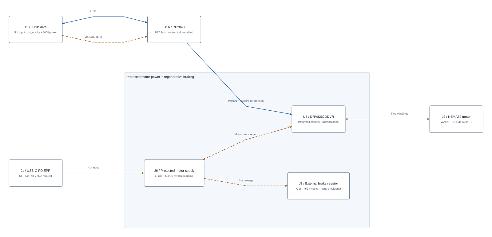
Design revision 0.5.0-RP2040-DRAFT — implementation and commissioning handoff. The source now uses RP2040, DRV8262DDVR with integrated power bridges, TPS26750 for the retained 48 V / 5 A EPR input, and an optional AS5600. The stocked-driver ECO follows merged PR #27 (5035034) and retains that 48 V architecture. Use the assembly and commissioning guides below to prepare the order and collect physical results after assembly.
Start with the nine-sheet power/component review, current reference-board decisions, the redesign and evidence, reviewer checklist and firmware instructions. index.circuit.tsx is the current schematic/placement source. The DATA-only source, firmware and native route are synchronized. The paired native review archive contains fresh DRC/ERC reports: 8 retained USB hole-clearance errors, 488 cosmetic warnings, and zero other errors, unconnected items or schematic-parity/ERC findings. The older GUI screenshot is explicitly historical.
The new commissioning firmware is an ARM RP2040 image with verified ELF/BIN/UF2 format and matching source hashes. The default image remains diagnostics-only. Separate stationary-power and bounded motor-test profiles provide the post-assembly workflow: <=0.8 A RMS request, 10 rpm, 10 seconds, local START and automatic stop. Use programming, readback and commissioning. Physical measurements are performed by the assembly/test team; the software results do not claim them.
The hosted preview opens release/circuit.json; its routed payload has been regenerated from the verified native board and checked against this DATA-only source. index.circuit.tsx remains editable; bun run dev opens that source. The PCB carries the matching 0.5 DRAFT revision marking.
| Function | This design |
|---|---|
| U16 MCU / U17 boot storage | RP2040 / W25Q32JV, 4 MiB QSPI flash, 12 MHz crystal; powered only from J10 DATA |
| U7 motor stage | DRV8262DDVR, top-cooled DDV package; PH/EN motion with U42 MCP4822 dual current references |
| Power | TPS26750 EPR sink, dedicated J1; independent DATA/logic-power J10 |
| PD monitoring | U38 INA237 measures raw PD_VBUS; ADS1115 retains protected VMOTOR. Fresh ADC conversion + TPS contract produce PD_READY; eFuse MOTOR_PG stays independent. |
| Terminals | J2 WAGO 2601-3104 motor; J3 WAGO 236-402 brake. No JST mating plugs; paired solder tails belong to each wire entry. |
| Encoder | AS5600 I²C, optional DNP U18 on bottom; C52/C53 on top |
| Protection | Independent eFuse, voltage window, thermal inhibit, hardware enable gates and external J3 braking resistor retained |
| Motor | STEPPERONLINE 34HS31-6004S1, 6 A/phase motor rating; initial bench-test requests <=0.8 A RMS |
| Mounting | Four motor-CAD-aligned holes; choose screws/spacers from measured rear thread/depth and physical fit |
For order preparation, use fabrication and assembly instructions, the exact-part sourcing snapshot and manufacturer acceptance checklist. They separate the supplied files/software from supplier allocation, installation and post-assembly measurements.
Source/firmware development checks:
bun install --frozen-lockfile
bunx tsci build index.circuit.tsx --routing-disabled --disable-parts-engine
bun run typecheck
bun run check:firmware-pins
bun run check:firmware
bun test scripts/rp2040-contract.test.mjs scripts/encoder-bypass-policy.test.mjs
bun run check:schematic-style
Run bun run review for all engineering and artifact checks; consult its generated report. The machine-readable release record separately retains manufacturer acceptance, sourcing and physical-test evidence.
The completed reviewer scope and remaining physical acceptance steps are in the handoff. The ordered-motor manufacturer STEP archive establishes the rear hole axes; it does not approve replacement screws or engagement depth.
Previous-board context: historical README. It is retained for review, not as evidence for the redesign.
DATA-only MCU: J10 supplies RP2040 even when J1 PD is connected. PD alone cannot run local controls. Board-side I²C and status signals are isolated through U39/U40; the brake retains independent motor-bus power. See power domains.
| Qty | Value | Footprint | References |
|---|---|---|---|
| 39 | 100nF | capacitor_cap0603 | C1, C10, C12, C14, C20, C24, C28, C38, C39, C40, C41, C109, C110, C111, C112, C114 +23 |
| 27 | 10kΩ | resistor_res0603 | R1, R14, R18, R21, R24, R28, R29, R30, R104, R111, R114, R131, R132, R133, R148, R149 +11 |
| 14 | 4.7kΩ | resistor_res0603 | R3, R4, R5, R6, R7, R22, R128, R129, R130, R140, R141, R142, R143, R144 |
| 13 | 1uF | capacitor_cap0603 | C2, C13, C18, C27, C29, C42, C53, C64, C75, C88, C93, C113, C115 |
| 12 | 100kΩ | resistor_res0603 | R2, R11, R13, R15, R16, R67, R69, R102, R113, R121, R127, R145 |
| 10 | 100nF | capacitor_cap0402 | C44, C45, C46, C100, C101, C104, C105, C106, C107, C108 |
| 9 | 22uF | capacitor_cap0805 | C15, C16, C17, C66, C67, C68, C90, C91, C92 |
| 6 | 10uF | capacitor_cap0603 | C6, C7, C8, C71, C76, C96 |
| 6 | 1kΩ | resistor_res0603 | R117, R118, R123, R126, R138, R139 |
| 4 | hole_circle_holeDiameter4.2mm | , , , | |
| 4 | 180kΩ | resistor_res0603 | R19, R20, R31, R32 |
| 4 | 2.2uF | capacitor_cap1206 | C11, C21, C62, C86 |
| 4 | SN74LVC1G08DBVR | SN74LVC1G08DBVR | U4, U10, U11, U33 |
| 3 | 100nF | capacitor_cap0805 | C25, C26, C30 |
| 3 | 10nF | capacitor_cap0603 | C83, C84, C98 |
| 3 | 20kΩ | resistor_res0603 | R26, R33, R65 |
| 3 | LM66100DCKR | LM66100DCKR | U23, U24, U27 |
| 3 | LMR36510ADDAR | LMR36510ADDAR | U5, U22, U34 |
| 2 | 0Ω | resistor_res0603 | R9, R12 |
| 2 | 1.5kΩ | resistor_res0603 | R146, R147 |
| 2 | 1000uF | EEUFS1J102 | C22, C23 |
| 2 | 15pF | capacitor_cap0603 | C49, C50 |
| 2 | 1MΩ | resistor_res0603 | R63, R107 |
| 2 | 1uF | capacitor_cap0402 | C102, C103 |
| 2 | 220pF | capacitor_cap0603 | C3, C4 |
| 2 | 22µH | SWPA6045S220MT | L1, L2 |
| 2 | 27Ω | resistor_res0603 | R71, R72 |
| 2 | 330Ω | resistor_res0603 | R124, R125 |
| 2 | 4.7kΩ | resistor_res1206 | R134, R135 |
| 2 | 4.7uF | capacitor_cap1206 | C5, C47 |
| 2 | 43.2kΩ | resistor_res0603 | R17, R103 |
| 2 | 47kΩ | resistor_res0603 | R108, R137 |
| 2 | 5.1kΩ | resistor_res0603 | R105, R106 |
| 2 | 5mΩ | FRM121WFR005TM | R115, R116 |
| 2 | BSS123LT1G | BSS123LT1G | Q1, Q5 |
| 2 | CSD17484F4 | CSD17484F4 | Q2, Q3 |
| 2 | CSD19534Q5A | CSD19534Q5A | Q4, Q16 |
| 2 | INA240A1DR | INA240A1DR | U31, U32 |
| 2 | TLV3201AIDBVR | TLV3201AIDBVR | U13, U14 |
| 2 | TS-1088-AR02016 | TS-1088-AR02016 | SW1, SW2 |
| 2 | USB4105-GF-A-060 | USB4105-GF-A-060 | J1, J10 |
| 1 | 1.2kΩ | resistor_res0603 | R66 |
| 1 | 10Ω | resistor_res0603 | R68 |
| 1 | 16.2kΩ | resistor_res0603 | R61 |
| 1 | 180kΩ | resistor_res0805 | R60 |
| 1 | 220nF | capacitor_cap0805 | C87 |
| 1 | 236-402 | 236-402 | J3 |
| 1 | 2601-3104 | 2601-3104 | J2 |
| 1 | 360kΩ | resistor_res0603 | R27 |
| 1 | 4.99kΩ | resistor_res0603 | R25 |
| 1 | 422kΩ | resistor_res0603 | R23 |
| 1 | 430kΩ | resistor_res0603 | R64 |
| 1 | 47µH | SRP7050TA-470M | L3 |
| 1 | 510Ω | resistor_res0603 | R136 |
| 1 | 9.09kΩ | resistor_res0603 | R122 |
| 1 | ABM8-272-T3 | ABM8-272-T3 | Y1 |
| 1 | ADS1115IDGSR | ADS1115IDGSR | U30 |
| 1 | AO3400A | AO3400A | Q26 |
| 1 | AS5600-ASOM | AS5600-ASOM | U18 |
| 1 | D | SS10100 | D20 |
| 1 | D | BAV21W-7-F | D18 |
| 1 | DRV8262DDVR | DRV8262DDVR | U7 |
| 1 | FMB09A03-3V | FMB09A03-3V | BZ1 |
| 1 | INA237AIDGSR | INA237AIDGSR | U38 |
| 1 | M24512-RMN6TP | M24512-RMN6TP | U3 |
| 1 | MCP4822-E/SN | MCP4822-E_SN | U42 |
| 1 | NH-B2020RGBA-HF | NH-B2020RGBA-HF | D16 |
| 1 | PCA9538PWR | PCA9538PWR | U35 |
| 1 | REF3425IDBVR | REF3425IDBVR | U12 |
| 1 | RP2040 | RP2040 | U16 |
| 1 | SN74LVC1G17DBVR | SN74LVC1G17DBVR | U37 |
| 1 | SN74LVC244APWR | SN74LVC244APWR | U40 |
| 1 | SN74LVC2G66DCTR | SN74LVC2G66DCTR | U36 |
| 1 | TCA9517ADGKR | TCA9517ADGKR | U39 |
| 1 | TLV75533PDBVR | TLV75533PDBVR | U25 |
| 1 | TMP102AIDRLR | TMP102AIDRLR | U29 |
| 1 | TPD4S480RUKR | TPD4S480RUKR | U1 |
| 1 | TPS22919DCKR | TPS22919DCKR | U41 |
| 1 | TPS2553DBVR | TPS2553DBVR | U28 |
| 1 | TPS26630RGER | TPS26630RGER | U6 |
The 252 most common of 277 parts.
It measures 85.9 × 85.9 mm and has 4 copper layers, 1.6 mm thick.
277 parts, built around the RP2040, SN74LVC244APWRE4, ADS1115IDGSR and AS5600-ASOM. The full list of its parts is on this page, with links to each part's symbol and footprint where PCBKit's library has them.
From the techmannih/pd1180-epr repository on GitHub, at the commit this page was made from: the board is dist/manufacturing/kicad-project/pd1180-epr-r0.3.kicad_pcb and its schematic dist/manufacturing/kicad-project/brake.kicad_sch. PCBKit opens the board in the browser, with nothing to install.
Its repository states no licence, so its author keeps all rights: ask techmannih before reusing the design.
, the printed circuit board in 3D](/embed/boards/lattepandateam-lattepanda-mu-dfr1144-m027-00940-v1-0-0.jpg?size=s&soon)
LattePandaTeam/LattePanda-Mu
All About LattePanda Mu N100/N305 Compute Module

ForestKatsch/unofficial-tesla-seat-controller
STM32G0-based controller for four seat motors, two ventilation fans, and the seat switchpack. Input is a regulated 12 V Mean Well power supply; record the exact model before system testing.

JGilcreast/MetalHead
An opensource firmware and software drop-in replacement for the 85V Automatic Stirrup Bender by CRS Specialties Inc. ...short story behind the name...


enkhbold470/iron-node
ESP32-S3 industrial gateway: W5500 Ethernet, isolated RS-485 (ADM2587E), CAN, 9-36 V input. 4-layer KiCad 10 board.

CopycatMusic/ComposerMIDICV
4 HP Eurorack USB/TRS MIDI-to-CV module: RP2354A firmware, KiCad hardware and v1.0 manufacturing files.