

2 layers130 × 80 mm

 sudhitpopli/Audio-Pre-Amplifier
This repository contains the design files and simulation for an Audio Pre-Amplifier project.
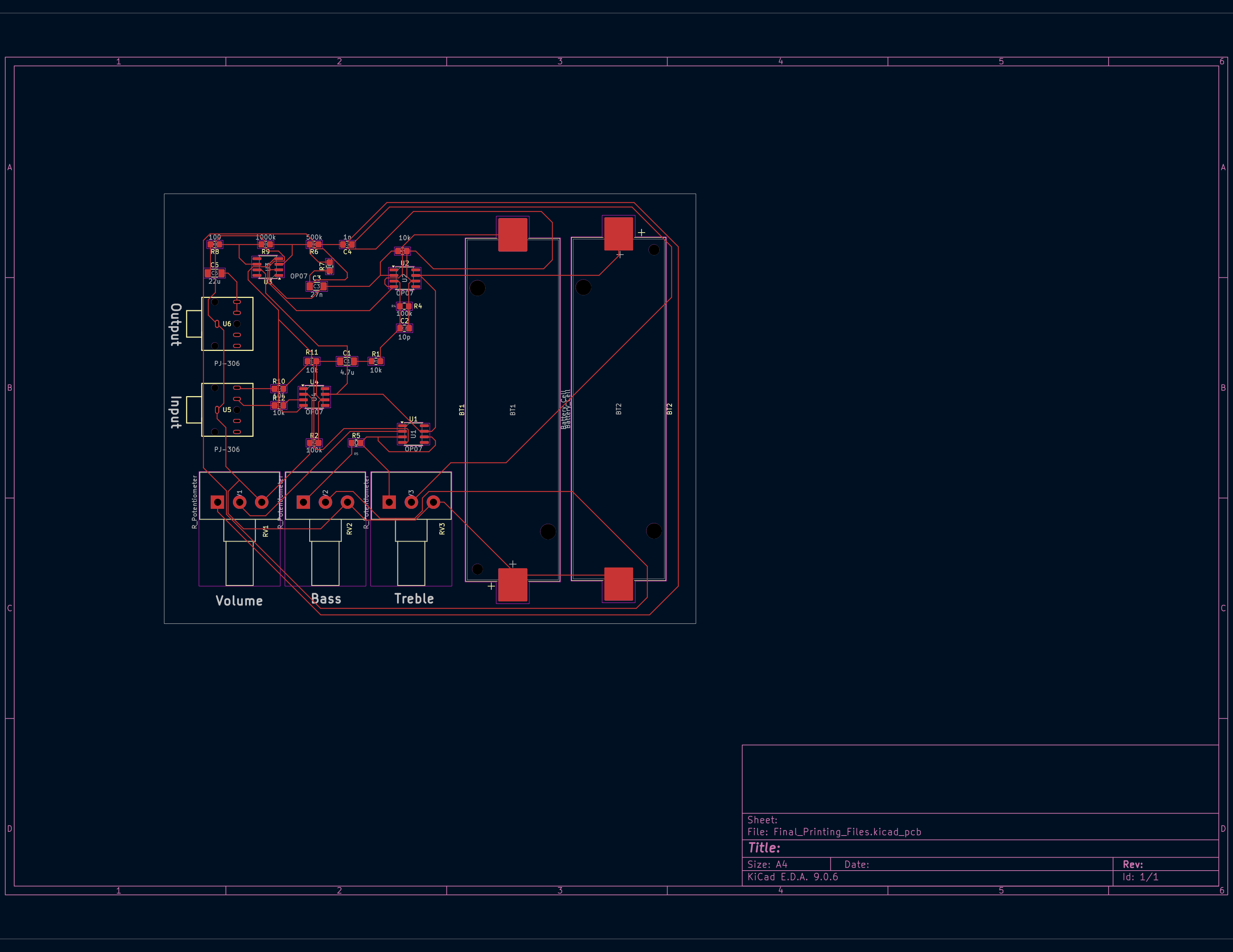
Final Printing Files is an open-source printed circuit board by sudhitpopli, from the sudhitpopli/Audio-Pre-Amplifier repository on GitHub. It is a 2-layer board of 120.5 × 97.5 mm with 28 parts on 36 nets, routed with 242 tracks and 0 vias.
It is built around the OP07 and PJ-306. Its parts include 12 resistors, 6 ICs and 5 capacitors.
This repository contains the design files and simulation for an Audio Pre-Amplifier project.
An audio pre-amplifier amplifies low-level signals from microphones or instruments to a line-level signal suitable for further processing or power amplification.
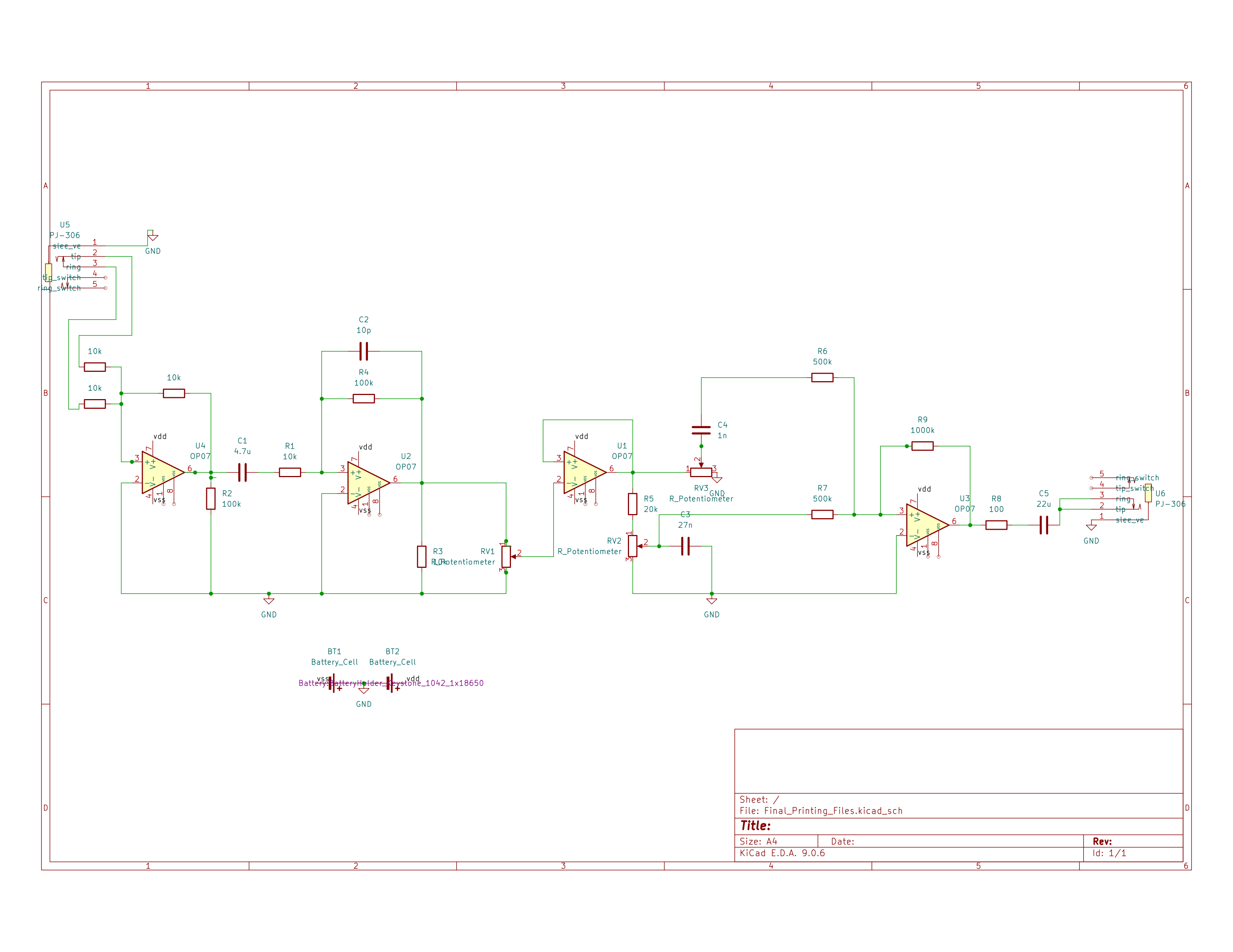
This circuit utilizes four OP07 operational amplifiers to amplify audio signals before feeding them into speakers. It features a built-in equalizer, allowing the user to selectively amplify specific frequency ranges using potentiometers.
How It Works:
Schematic
PCB Layout
Kicad Files/: This directory contains the complete KiCad project for the pre-amplifier, including the schematic (.kicad_sch) and the PCB layout (.kicad_pcb).LTSpice_Simulation_File.asc: An LTSpice simulation file used to verify the circuit design and frequency response before proceeding to physical design.Final_Printing_Files.zip: A compressed archive containing the generated files (likely Gerbers and drill files) ready to be sent to a PCB manufacturer.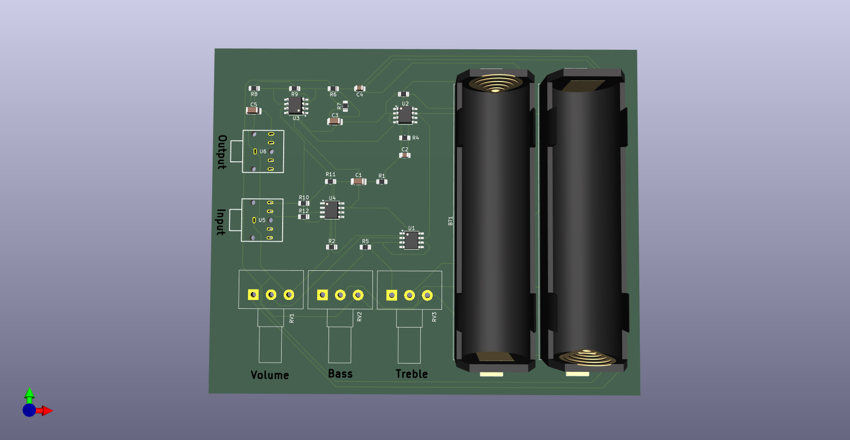
| Qty | Value | Footprint | References |
|---|---|---|---|
| 5 | 10k | Resistor_SMD:R_0805_2012Metric_Pad1.20x1.40mm_HandSolder | R1, R3, R10, R11, R12 |
| 4 | OP07 | Package_SO:SOIC-8_3.9x4.9mm_P1.27mm | U1, U2, U3, U4 |
| 3 | R_Potentiometer | Potentiometer_THT:Potentiometer_Alps_RK163_Single_Horizontal | RV1, RV2, RV3 |
| 2 | 100k | Resistor_SMD:R_0805_2012Metric_Pad1.20x1.40mm_HandSolder | R2, R4 |
| 2 | 500k | Resistor_SMD:R_0805_2012Metric_Pad1.20x1.40mm_HandSolder | R6, R7 |
| 2 | Battery_Cell | Battery:BatteryHolder_Keystone_1042_1x18650 | BT1, BT2 |
| 2 | PJ-306 | easyeda2kicad:AUDIO-TH_PJ-306 | U5, U6 |
| 1 | 100 | Resistor_SMD:R_0805_2012Metric_Pad1.20x1.40mm_HandSolder | R8 |
| 1 | 1000k | Resistor_SMD:R_0805_2012Metric_Pad1.20x1.40mm_HandSolder | R9 |
| 1 | 10p | Capacitor_SMD:C_0805_2012Metric_Pad1.18x1.45mm_HandSolder | C2 |
| 1 | 1n | Capacitor_SMD:C_0805_2012Metric_Pad1.18x1.45mm_HandSolder | C4 |
| 1 | 20k | Resistor_SMD:R_0805_2012Metric_Pad1.20x1.40mm_HandSolder | R5 |
| 1 | 22u | Capacitor_SMD:C_1206_3216Metric_Pad1.33x1.80mm_HandSolder | C5 |
| 1 | 27n | Capacitor_SMD:C_1206_3216Metric_Pad1.33x1.80mm_HandSolder | C3 |
| 1 | 4.7u | Capacitor_SMD:C_1206_3216Metric_Pad1.33x1.80mm_HandSolder | C1 |


SP6GK/Forte-600-HF-RF-Amplifier
Project of 600 W LDMOS amlifier based on 2xMRF300.


bash227/ECG-Motor-Control-Power-Management-PCB
A multi-function PCB integrating biomedical signal acquisition (ECG), DC motor control, and advanced power management for wearable applications.
It measures 120.5 × 97.5 mm and has 2 copper layers, 1.6 mm thick.
28 parts, built around the OP07 and PJ-306. The full list of its parts is on this page, with links to each part's symbol and footprint where PCBKit's library has them.
From the sudhitpopli/Audio-Pre-Amplifier repository on GitHub, at the commit this page was made from: the board is Kicad Files/Final_Printing_Files.kicad_pcb and its schematic Kicad Files/Final_Printing_Files.kicad_sch. PCBKit opens the board in the browser, with nothing to install.
Its repository states no licence, so its author keeps all rights: ask sudhitpopli before reusing the design.