2 layers144.8 × 88.9 mm

 iorodeo/potentiostat57
Rodeostat design files, software and firmware
Potentiostat is an open-source printed circuit board by iorodeo, from the iorodeo/potentiostat repository on GitHub, published under the CC-BY-4.0 licence. It is a 2-layer board of 144.8 × 88.9 mm with 142 parts on 132 nets, routed with 1,373 tracks and 70 vias.
It is built around the OP07, TL072 and 74HC138. Its parts include 52 capacitors, 38 resistors, 22 connectors, 20 ICs and 2 diodes.


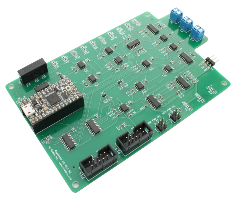
Hardware design, firmware and software for IO Rodeo's Rodeostat Potentiostat.
| Qty | Value | Footprint | References |
|---|---|---|---|
| 39 | 0.1uF | Capacitor_SMD:C_0603_1608Metric | C2, C3, C10, C11, C12, C13, C14, C15, C16, C17, C18, C19, C20, C21, C24, C31 +23 |
| 15 | Conn_01x02 | pin_array:PIN_ARRAY_2X1 | P4, P5, P6, P7, P8, P9, P10, P11, P12, P17, P18, P19, P20, P21, P22 |
| 9 | 10k | Resistor_SMD:R_0603_1608Metric | R6, R7, R9, R18, R19, R24, R33, R34, R36 |
| 9 | OP07 | Package_SO:SOIC-8_3.9x4.9mm_P1.27mm | U11, U12, U13, U14, U15, U16, U17, U18, U20 |
| 8 | 20k | Resistor_SMD:R_0603_1608Metric | R3, R4, R5, R8, R10, R13, R23, R25 |
| 5 | DG411xY | Package_SO:SOIC-16_3.9x9.9mm_P1.27mm | U3, U4, U5, U7, U8 |
| 4 | 33k | Resistor_SMD:R_0603_1608Metric | R1, R2, R26, R28 |
| 4 | 56nF | Capacitor_SMD:C_0603_1608Metric | C25, C26, C27, C28 |
| 4 | VAL** | 4-40 | H1, H2, H3, H4 |
| 3 | 100k | Resistor_SMD:R_0603_1608Metric | R12, R20, R21 |
| 3 | 2.2uF | Capacitor_SMD:C_0603_1608Metric | C7, C8, C9 |
| 3 | 74HC138 | Package_SO:SOIC-16_3.9x9.9mm_P1.27mm | U1, U19, U21 |
| 3 | Conn_01x02 | ost_connblocks:CONNBLOCK2 | P1, P2, P3 |
| 2 | 100 | Resistor_SMD:R_0603_1608Metric | R31, R38 |
| 2 | 1k | Resistor_SMD:R_0603_1608Metric | R30, R37 |
| 2 | 1uF | Capacitor_SMD:C_0603_1608Metric | C22, C23 |
| 2 | 4.7k | Resistor_SMD:R_0603_1608Metric | R32, R35 |
| 2 | 50k | Resistor_SMD:R_0603_1608Metric | R11, R22 |
| 2 | BAS07-04 | Package_TO_SOT_SMD:SOT-23 | D1, D2 |
| 2 | Conn_02x02_Odd_Even | pin_array:PIN_ARRAY_2X2 | P15, P16 |
| 2 | Conn_02x05_Odd_Even | 5x2_shrd_header:5X2_SHRD_HEADER | P13, P14 |
| 2 | header_14_pos | dummy:header_14_pos | UA2, UB2 |
| 1 | 10nF | Capacitor_SMD:C_0603_1608Metric | C29 |
| 1 | 11k | Resistor_SMD:R_0603_1608Metric | R29 |
| 1 | 12nF | Capacitor_SMD:C_0603_1608Metric | C30 |
| 1 | 2k | Resistor_SMD:R_0603_1608Metric | R27 |
| 1 | 3.3nF | Capacitor_SMD:C_0603_1608Metric | C6 |
| 1 | 300 | Resistor_SMD:R_0603_1608Metric | R17 |
| 1 | 300k | Resistor_SMD:R_0603_1608Metric | R14 |
| 1 | 30k | Resistor_SMD:R_0603_1608Metric | R15 |
| 1 | 3k | Resistor_SMD:R_0603_1608Metric | R16 |
| 1 | 4.7uF | Capacitor_SMD:C_0603_1608Metric | C5 |
| 1 | Conn_01x03 | pin_array:PIN_ARRAY_3X1 | K1 |
| 1 | ITSY_BITSY_M4 | itsy_bitsy_m4:ITSY_BITSY_M4 | U2 |
| 1 | MEA1D05XXSC | MEA1:MEA1 | U6 |
| 1 | TL072 | Package_SO:SOIC-8_3.9x4.9mm_P1.27mm | U9 |
| 1 | header_5_pos | dummy:header_5_pos | UC2 |


CrafterSteve/ESP32_Temp_Con
An temperture control device, based on ESP32. With custom PCB board, it can fit an ESP32-DevKit as controller, DAC and ADC is done on board, as well as, a 5 to +-12v power supply..


rjw57/buri
This repository contains my work on designing, building and programming a 6502 microcomputer from scratch. The 6502 was the CPU used in the original Apple 1, BBC Microcomputer, NES console and many other systems from…


SP6GK/Forte-600-HF-RF-Amplifier
Project of 600 W LDMOS amlifier based on 2xMRF300.

It measures 144.8 × 88.9 mm and has 2 copper layers, 1.6 mm thick.
142 parts, built around the OP07, TL072 and 74HC138. The full list of its parts is on this page, with links to each part's symbol and footprint where PCBKit's library has them.
From the iorodeo/potentiostat repository on GitHub, at the commit this page was made from: the board is hardware/pcbs/itsy_bitsy_mx_shield_v0p1/low_current/potentiostat.kicad_pcb. PCBKit opens the board in the browser, with nothing to install.
Its repository publishes it under the CC-BY-4.0 licence: you may reuse it on that licence's terms (keep the author's notice, and for a copyleft licence share your changes alike).