
2 layers58.2 × 38.1 mm
Usb sniffer
ataradov/usb-sniffer
Low-cost LS/FS/HS USB sniffer with Wireshark interface
87 parts1.3kBSD-3-Clause

 st4rk-7/oscilite
Digital storage oscilloscope on STM32F407 with analog frontend, hardware-timed ADC+DMA, custom UI, and custom PCB shield.
FullScope is an open-source printed circuit board by st4rk-7, from the st4rk-7/oscilite repository on GitHub. It is a 2-layer board of 92 × 118 mm with 22 parts on 69 nets, routed with 185 tracks and 0 vias.
It is built around the BAT54S. Its parts include 5 resistors, 5 connectors, 4 capacitors, 4 switches and 2 ICs. It belongs with the sensors and measurement boards and the STM32 boards of this library.
A digital storage oscilloscope built from scratch on an STM32F407. This project covers the full stack of building a real instrument: analog signal conditioning → ADC sampling → DMA → triggering → rendering → custom PCB hardware design.
Currently running as a breadboard prototype with the V2 custom PCB shield designed and ready for fabrication.
The boot splash rendered on the 160×128 ST7735 TFT at power-on.
 The breadboard prototype running live firmware, capturing and displaying a waveform.
The current working prototype proves out the entire software stack and analog theory.
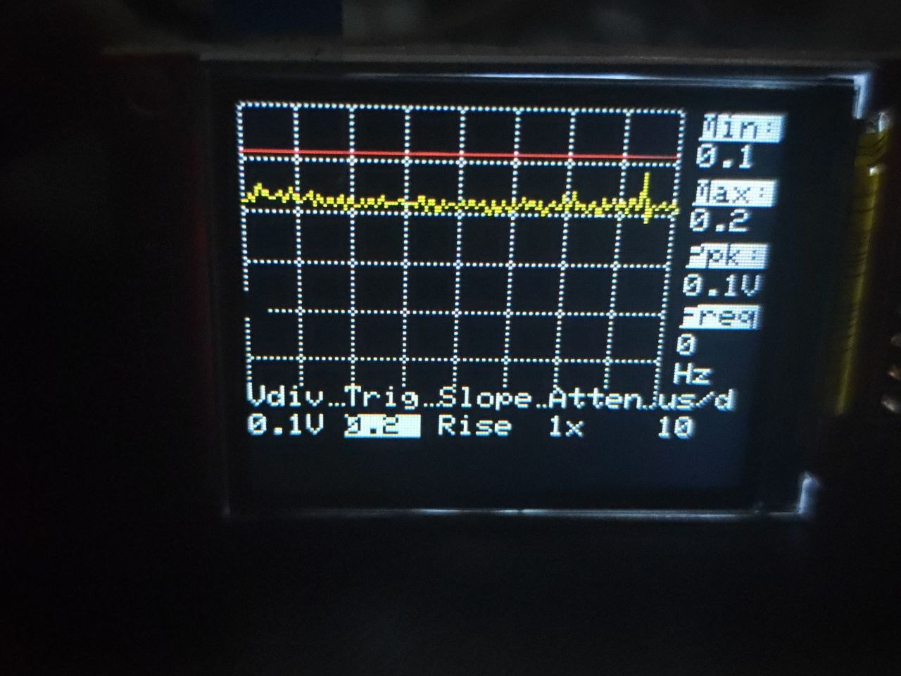 Full system context showing the STM32F407 Discovery board, the analog frontend, and the display.
How It Works:
 Input ─▶ Analog Frontend ─▶ ADC (12‑bit) ─▶ DMA ─▶ Sample Buffer ─▶ Trigger ─▶ Display
        (attenuate + bias)   (TIM3‑timed)   (circular)              (align)    (ILI9341)
The input signal is attenuated and centered at ~1.65 V using an MCP6002 op-amp buffer circuit so it fits the ADC's 0–3.3 V window. A timer fires the ADC at a fixed rate to set the timebase; the DMA engine moves each sample into a circular buffer without the CPU. The firmware then finds the trigger point (rising or falling through the trigger level) and draws the aligned waveform, computing min/max/Vpp and frequency along the way.
(A deeper write‑up of the theory is in docs/HowItWorks.md)
To move past the breadboard stage, a custom 2-layer PCB shield was designed in KiCad 10. The shield mounts directly onto the STM32F407 dev board headers, carrying the analog frontend, BNC connector, user buttons, and a header for the TFT display.
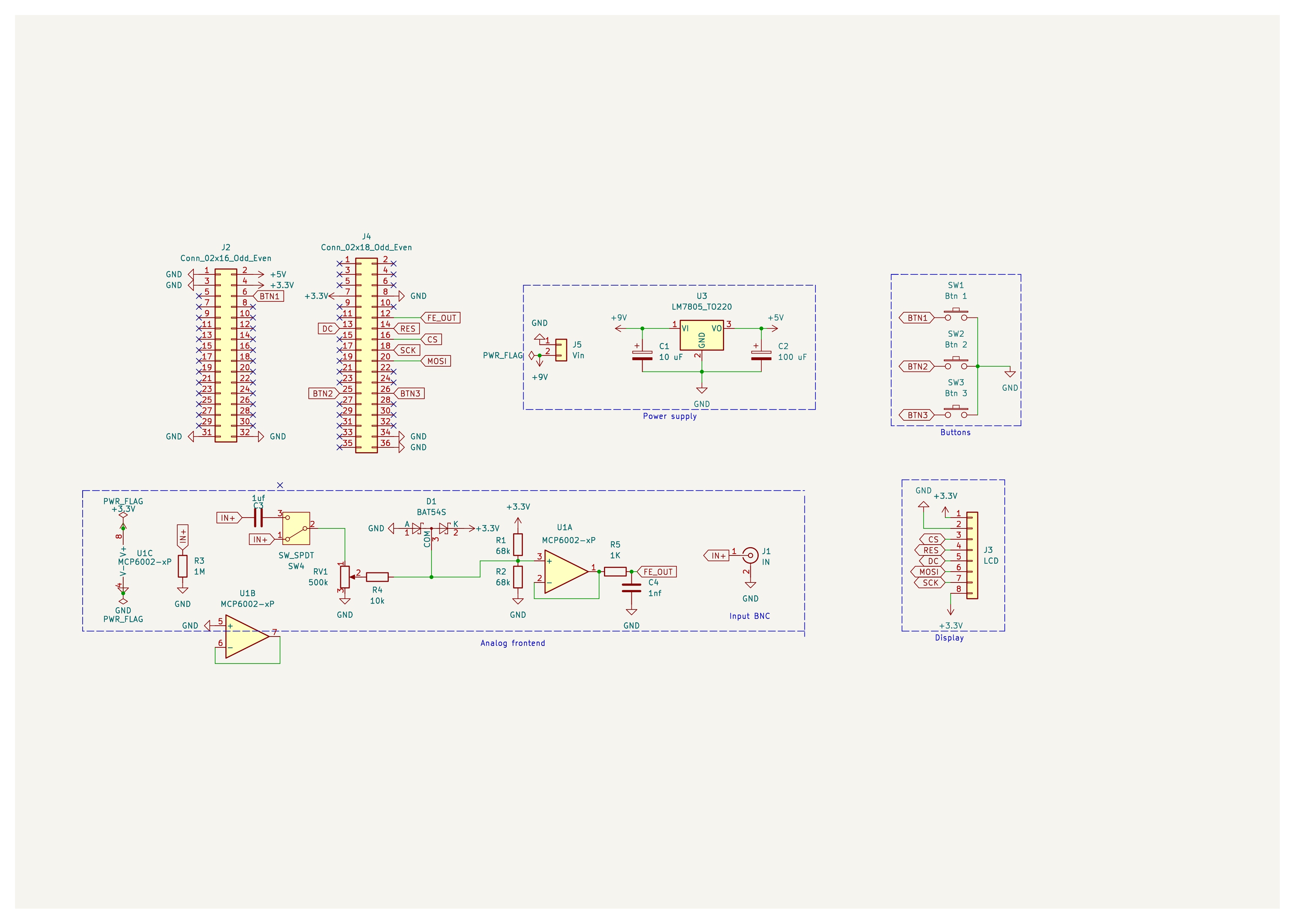
The analog frontend, power distribution, and UI circuitry.
The board is fully routed, DRC-clean, and the Gerbers are ready for manufacturing.
| Top Copper & Silkscreen | 3D Render (Top) |
|---|---|
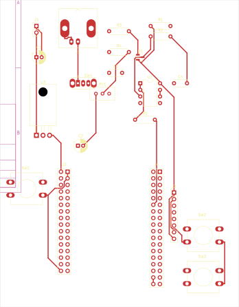 | 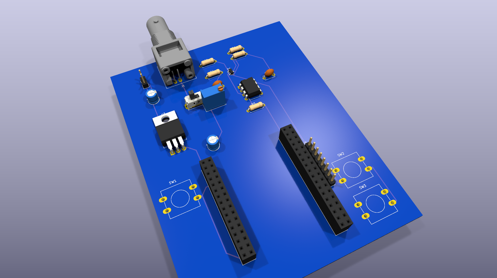 |
| Bottom Copper | 3D Render (Bottom) |
|---|---|
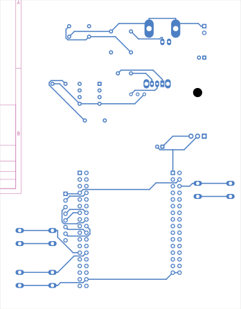 | 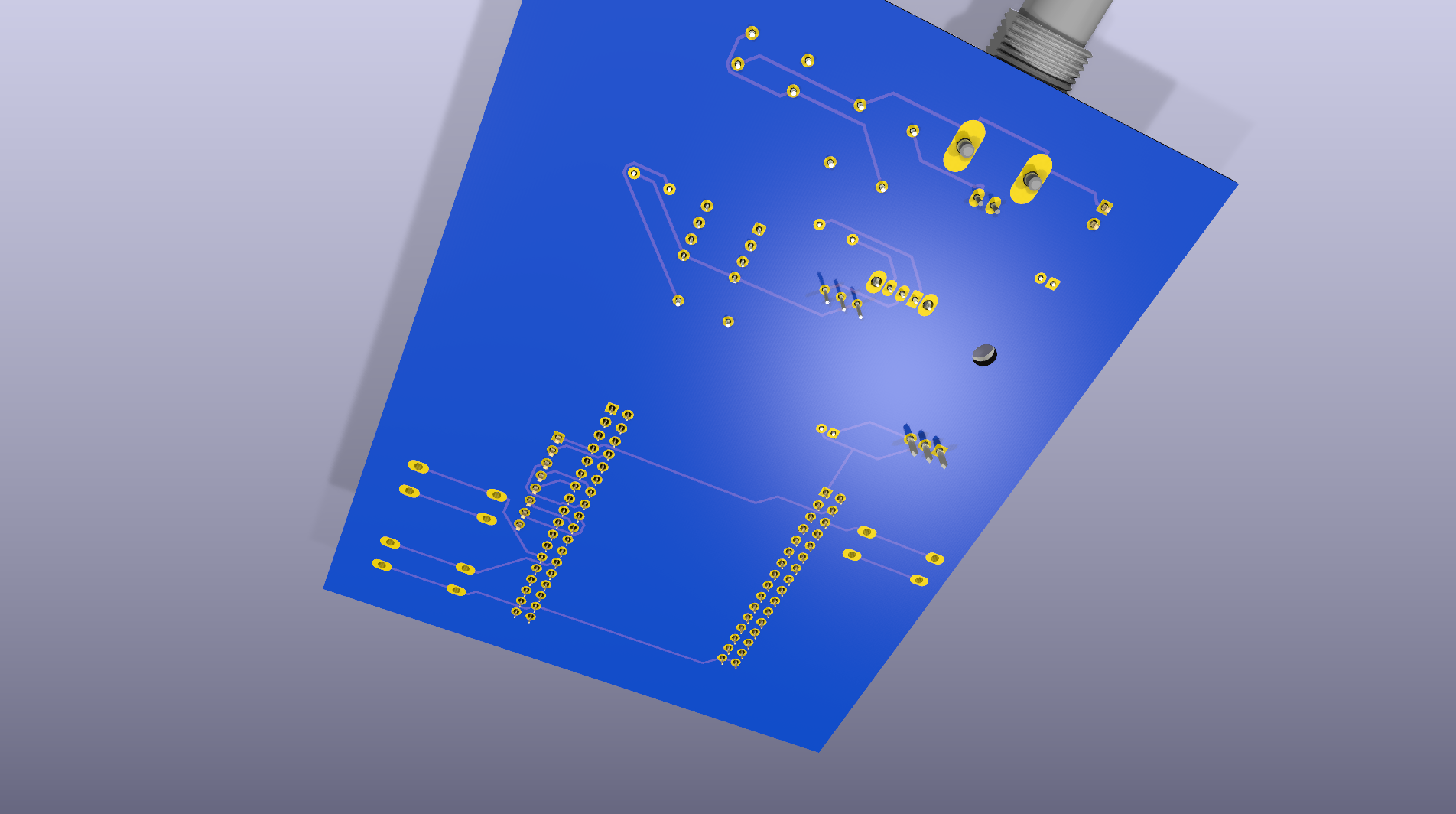 |
Note: The board relies on a dual-header layout designed specifically for the Diymore STM32F407VGT6 development board.
Core/Src/        Firmware: scope.c, ui.c, wave.c, adc.c, dma.c, tim.c, sandbox.c, main.c
Core/Inc/        Headers (scope.h defines grid, buffer length, trigger constants)
Drivers/         STM32 HAL + CMSIS + Display driver
pcb/fullScope/   KiCad project, layout, DRC reports, Gerbers
docs/            HowItWorks.md, PCB walkthrough
scripts/         Helper scripts (splash image conversion, UI patching)
Scopef407.ioc STM32CubeMX configurationPrerequisites:
Scopef407.ioc)arm-none-eabi-gcc)Build:
# Configure (uses the provided CMake presets)
cmake --preset Debug

# Build
cmake --build build/Debug
Flash it with your tool of choice, e.g.:
st-flash write build/Debug/Scopef407.bin 0x8000000This is intentionally a hands-on learning project to understand the full stack of instrument creation, not a precision lab tool.
Built on the STM32 HAL and CMSIS.
| Qty | Value | Footprint | References |
|---|---|---|---|
| 2 | 68k | Resistor_THT:R_Axial_DIN0207_L6.3mm_D2.5mm_P7.62mm_Horizontal | R1, R2 |
| 1 | 10 uF | Capacitor_THT:CP_Radial_D5.0mm_P2.00mm | C1 |
| 1 | 100 uF | Capacitor_THT:CP_Radial_D5.0mm_P2.00mm | C2 |
| 1 | 10k | Resistor_THT:R_Axial_DIN0207_L6.3mm_D2.5mm_P7.62mm_Horizontal | R4 |
| 1 | 1K | Resistor_THT:R_Axial_DIN0207_L6.3mm_D2.5mm_P7.62mm_Horizontal | R5 |
| 1 | 1M | Resistor_THT:R_Axial_DIN0207_L6.3mm_D2.5mm_P7.62mm_Horizontal | R3 |
| 1 | 1nf | Capacitor_THT:C_Disc_D5.0mm_W2.5mm_P5.00mm | C4 |
| 1 | 1uf | Capacitor_THT:C_Disc_D5.0mm_W2.5mm_P5.00mm | C3 |
| 1 | 500k | Potentiometer_THT:Potentiometer_Bourns_3296W_Vertical | RV1 |
| 1 | BAT54S | Package_TO_SOT_SMD:SOT-23 | D1 |
| 1 | Btn 1 | Button_Switch_THT:SW_PUSH-12mm | SW1 |
| 1 | Btn 2 | Button_Switch_THT:SW_PUSH-12mm | SW2 |
| 1 | Btn 3 | Button_Switch_THT:SW_PUSH-12mm | SW3 |
| 1 | Conn_02x16_Odd_Even | Connector_PinSocket_2.54mm:PinSocket_2x16_P2.54mm_Vertical | J2 |
| 1 | Conn_02x18_Odd_Even | Connector_PinSocket_2.54mm:PinSocket_2x18_P2.54mm_Vertical | J4 |
| 1 | IN | Connector_Coaxial:BNC_Amphenol_B6252HB-NPP3G-50_Horizontal | J1 |
| 1 | LCD | Connector_PinHeader_2.54mm:PinHeader_1x08_P2.54mm_Vertical | J3 |
| 1 | LM7805_TO220 | Package_TO_SOT_THT:TO-220-3_Horizontal_TabDown | U3 |
| 1 | MCP6002-xP | Package_DIP:DIP-8_W7.62mm | U1 |
| 1 | SW_SPDT | Button_Switch_THT:SW_Slide_SPDT_Straight_CK_OS102011MS2Q | SW4 |
| 1 | Vin | Connector_PinHeader_2.54mm:PinHeader_1x02_P2.54mm_Vertical | J5 |
ataradov/usb-sniffer
Low-cost LS/FS/HS USB sniffer with Wireshark interface

Twisted-Fields/rp2040-motor-controller
A dual channel brushless motor controller based on the RP2040 microcontroller, designed in Kicad.

corygrant/dingoPDM
Hardware - dingoPDM is an open source, affordable automotive PDM (Power Distribution Module). Pre-assembled and tested units are available or the design can be used to build a DIY version.


DvidMakesThings/HW_PDNode-600-Pro
The PDNode-600 is a professional-grade, 600W USB Power Delivery Unit designed specifically for compact 10-inch rack systems, targeting embedded developers, homelab enthusiasts, test benches, and smart infrastructure.

CameraNexus/sitina1
Open-source 35mm full-frame (36mm x 24mm) CCD mirror-less interchangable lens camera (MILC). The original goal of this project was to create a digital camera back to convert SLR cameras to DSLR cameras, but has since…

16n-faderbank/16nx
16nx is a controller for musical instruments. Sixteen faders,MIDI over USB and jack, CV out, and I2C out. Based around RP2040.

It measures 92 × 118 mm and has 2 copper layers, 1.6 mm thick.
22 parts, built around the BAT54S. The full list of its parts is on this page, with links to each part's symbol and footprint where PCBKit's library has them.
From the st4rk-7/oscilite repository on GitHub, at the commit this page was made from: the board is pcb/fullScope/fullScope.kicad_pcb and its schematic pcb/fullScope/fullScope.kicad_sch. PCBKit opens the board in the browser, with nothing to install.
Its repository states no licence, so its author keeps all rights: ask st4rk-7 before reusing the design.