Skip to the content
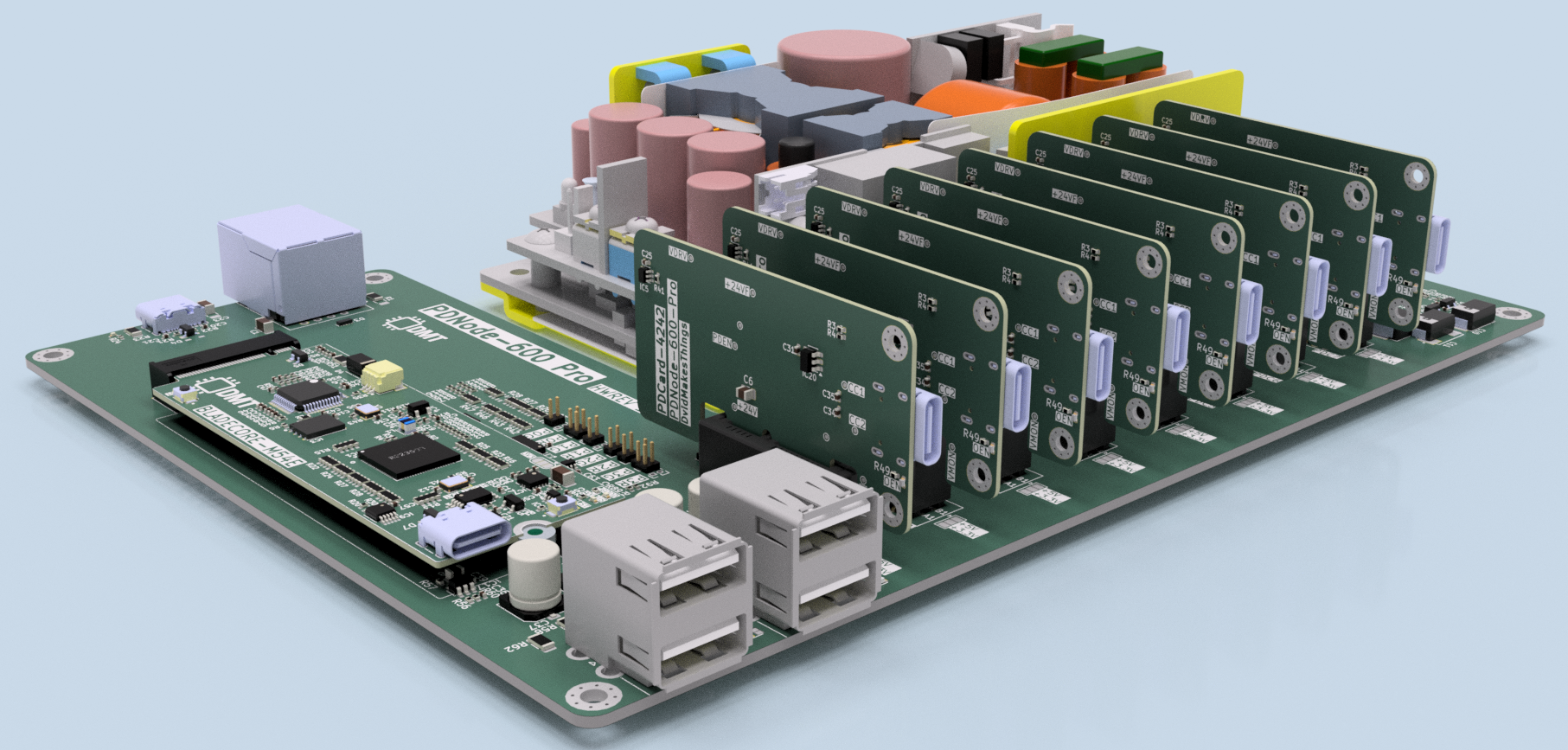
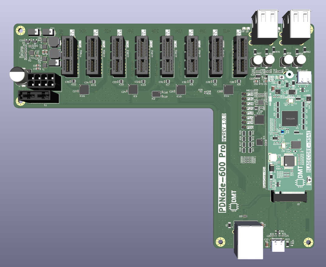
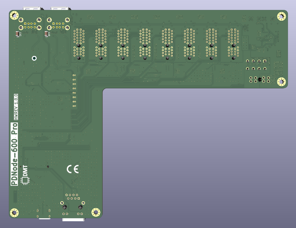
6 layers203 × 151.8 mmPDNode Baseboard, the printed circuit board in 3D

The PDNode-600 is a professional-grade, 600W USB Power Delivery Unit designed specifically for compact 10-inch rack systems, targeting embedded developers, homelab enthusiasts, test benches, and smart infrastructure.

Size
203 × 151.8 mm
Copper layers
6
Thickness
1.56 mm
Parts
236
Nets
289
Pads
1,479
Tracks, vias
4,097, 1,987
Pours
35
Routed
Yes
KiCad
KiCad 10.0 (file 20260206)
Created
2 May 2025
Updated
30 Mar 2026

Overview

PDNode Baseboard is an open-source printed circuit board by DvidMakesThings, from the DvidMakesThings/HW_PDNode-600-Pro repository on GitHub, published under the AGPL-3.0 licence. It is a 6-layer board of 203 × 151.8 mm with 236 parts on 289 nets, routed with 4,097 tracks and 1,987 vias.

It is built around the PAC1720-1-AIA-TR, TCA9548ARGER and TPS51225CRUKR, with the SN74LVC1G97QDCKRQ1, CD74HC4067QRGYRQ1 and 10018784-10200TLF among its other parts. Its parts include 85 resistors, 66 capacitors, 26 ICs, 23 connectors and 9 diodes. It belongs with the computers and single-board computers boards of this library.

Main components

12

README

README.md

PDNode-600 Pro

High-Performance USB PD Power Distribution Unit – 10" Rackmount

Hardware Development Status

Description

ENERGIS is the 230V managed PDU project. PDNode-600 Pro is the modular DC/USB-C sibling for setups where mains switching is not desired, but controllable, rack-friendly power output is still needed.

The PDNode-600 is a professional-grade, 600W USB Power Delivery Unit designed specifically for compact 10-inch rack systems, targeting embedded developers, homelab enthusiasts, test benches, and smart infrastructure. It delivers regulated, high-current power across 8x independent USB-C PD outputs and 4x fixed 5V USB-A outputs.

At the core of the PDNode platform is a centralized industrial-grade 24V/25A power supply, distributing regulated DC to dedicated per-port buck or buck-boost converters. Each USB-C port is managed by an MPQ4242-AEC1 PD controller, enabling clean, autonomous negotiation of power profiles up to 20V @ 3A or 5A with eMarker cable support. All power conversion, protection, and monitoring are designed to meet high reliability and safety standards.

The PDNode-600 Pro, by contrast, is built for remote-managed racks and headless environments, featuring Ethernet connectivity, a clean web-based UI, SNMP integration, and firmware updates via USB-C. Doing this by using BladeCore-M54E

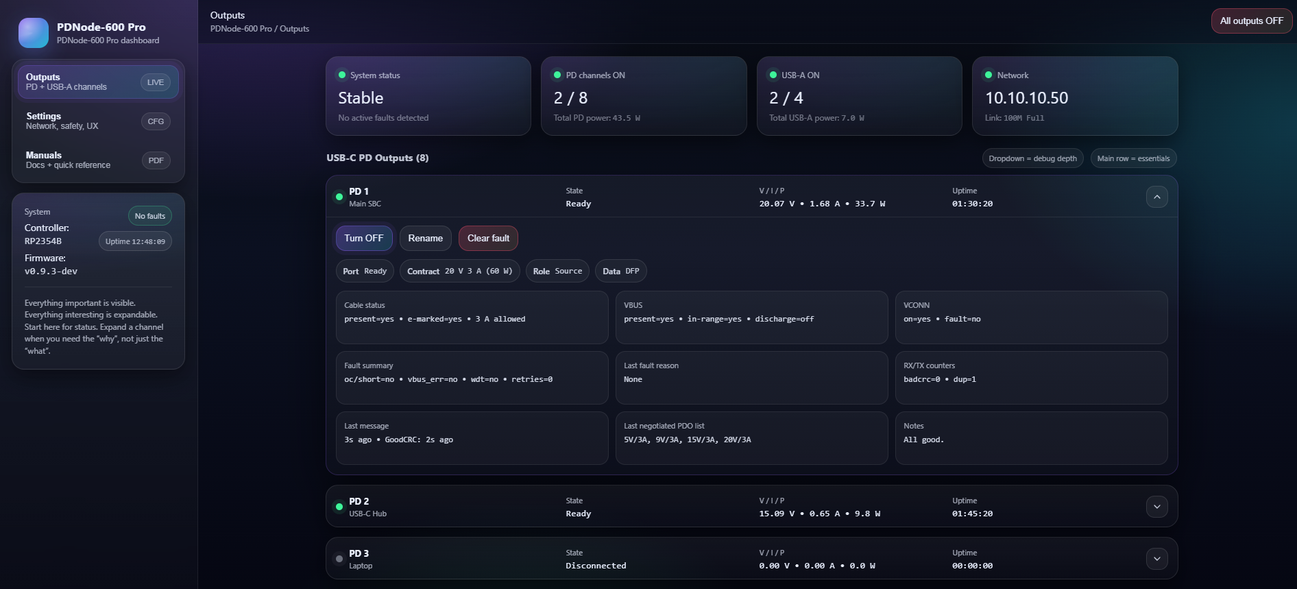
Web UI sneak peek

Interactive playground (dummy UI):

Try out the UI

Project timeline estimation

Status legend: ✅ Completed · 🟠 Ongoing · 🔵 Planned

#MilestonePlanned StartPlanned EndStatusNotes
1Architecture definition12-202501-2026✅ Completed
2Baseboard PCB design15-02-2026TBD✅ Completed
3PD card PCB design25-02-2026TBD✅ Completed
4Documentation12-20252026.12🟠 Ongoing
5PCB ordering01-03-202631-03-2026✅ CompletedWaiting for arrival
6Prototyping and hardware bring-up03-202630-04-2026🟠 Ongoing
7Firmware bring-up (slot scan, mux, PD iface)06-202611-2026🔵 Planned
8Telemetry and status reporting06-202611-2026🔵 Planned
9Validation (load, thermal, long-run)06-202611-2026🔵 Planned
10Integration and polishing06-202611-2026🔵 Planned
11Release package and final docs11-202612-2026🔵 Planned

Specifications

Input

  • Input voltage: 230 VAC, max 4A
  • System topology: 24V distribution on the baseboard, per-slot conversion on PD cards

Output (per PD card / per slot)

  • 8x independent USB-C PD source:
    • 5V 3A (5A only with 5A e-marked cable)
    • 9V 3A (5A only with 5A e-marked cable)
    • 12V 3A (5A only with 5A e-marked cable)
    • 15V 3A (5A only with 5A e-marked cable)
    • 20V 3A (5A only with 5A e-marked cable)
    • (Total power output cannot exceed 600W)
  • 4x USB-A source up to 5V / 1A per port (depending on configuration and limits)

Features

  • 8x independent USB-C PD source ports (modular PD cards, one port per slot)
  • Per-port PD profiles
  • Total system capability: up to 600W (shared input power budget)
  • 4x USB-A auxiliary outputs (5V, 1A per port) for low-power devices
  • Ethernet connectivity for control / monitoring
  • USB service interface (debug, configuration, firmware update, or log access depending on implementation)
  • Per-port power monitoring (current/voltage telemetry via onboard sensing)
  • Per-port status reporting (PGOOD / fault indication, and software-readable status)
  • Hot-swappable slot concept (cards can be replaced without redesigning the baseboard)

Hardware architecture

Baseboard

  • 24V DC input from industrial power supply
  • Power distribution to all slots (high-current bus)
  • Slot connectors + slot management (card detect, enable, status aggregation)
  • I2C fanout per slot (mux) for monitoring and controlling devices
  • Ethernet interface for user interaction
  • USB/service interface for debug/config/updates
  • 4x USB-A outputs
  • 8x USB-C PD outputs

BladeCore-M54E

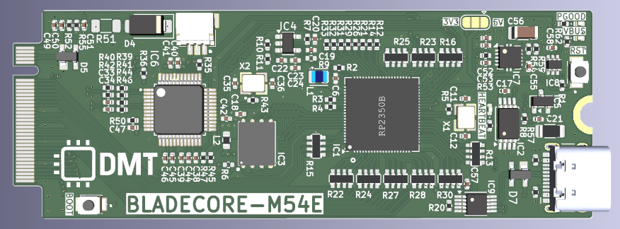
  • RP2354B microcontroller
  • External QSPI flash memory
  • External I²C EEPROM
  • 100BASE Ethernet via W5500
  • Dual‑path USB connectivity with automatic source selection
  • Onboard power regulation and defined power‑up sequencing
  • Compact M.2 M-key form factor

PD Card

  • 1x USB-C PD source port (one card = one port)
  • Local power conversion to generate VBUS from the 24V bus
  • PD controller + USB-C port control signals (enable, reset, IRQ)
  • Per-port current/voltage measurement
  • Per-port power good / fault status output
  • Optional ID EEPROM footprint (DNI) for traceability/calibration
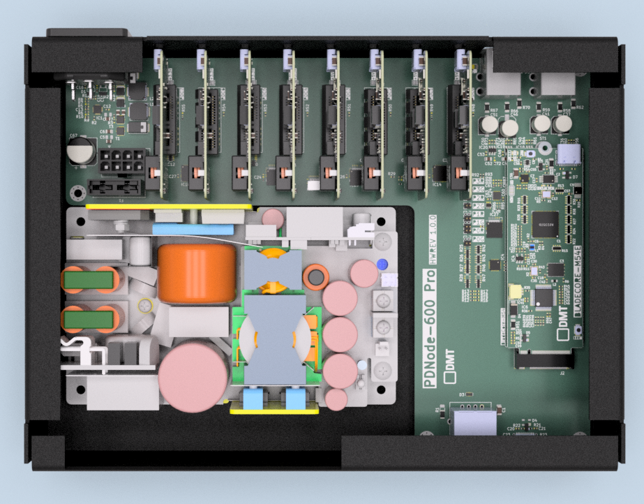
PDNode-600 Pro in Enclosure PDNode-600 Pro in Enclosure

Schematics

The full schematics are available:

PCB Documentation:


Development Phases (Hardware + Firmware)

Hardware PhaseStatusFirmware PhaseStatus
Architecture definition✅ CompletedSlot scan concept (TCA9548A)🔵 Planned
Baseboard PCB Design✅ CompletedI2C driver + mux control🔵 Planned
PD Card PCB Design✅ CompletedINA219 monitoring🔵 Planned
Documentation🟠 OngoingPD controller interface (SPI + GPIO)🔵 Planned
PCB ordering✅ CompletedTelemetry + status reporting🔵 Planned
Prototyping and Hardware Bring-up🟠 OngoingBring-up scripts / debug tooling🔵 Planned
Validation (load, thermal, long-run)🔵 PlannedError handling + fault reporting🔵 Planned
Production optimization🔵 PlannedIntegration and polishing🔵 Planned

Changelog

Rev0.1.0:
  • Initial design
  • STUSB4710 controller + TPS552882
Rev1.0.0:
  • Full redesign. STUSB4710 became EOL, need to use different PD controller
  • New concept: modular Baseboard + PDCard architecture
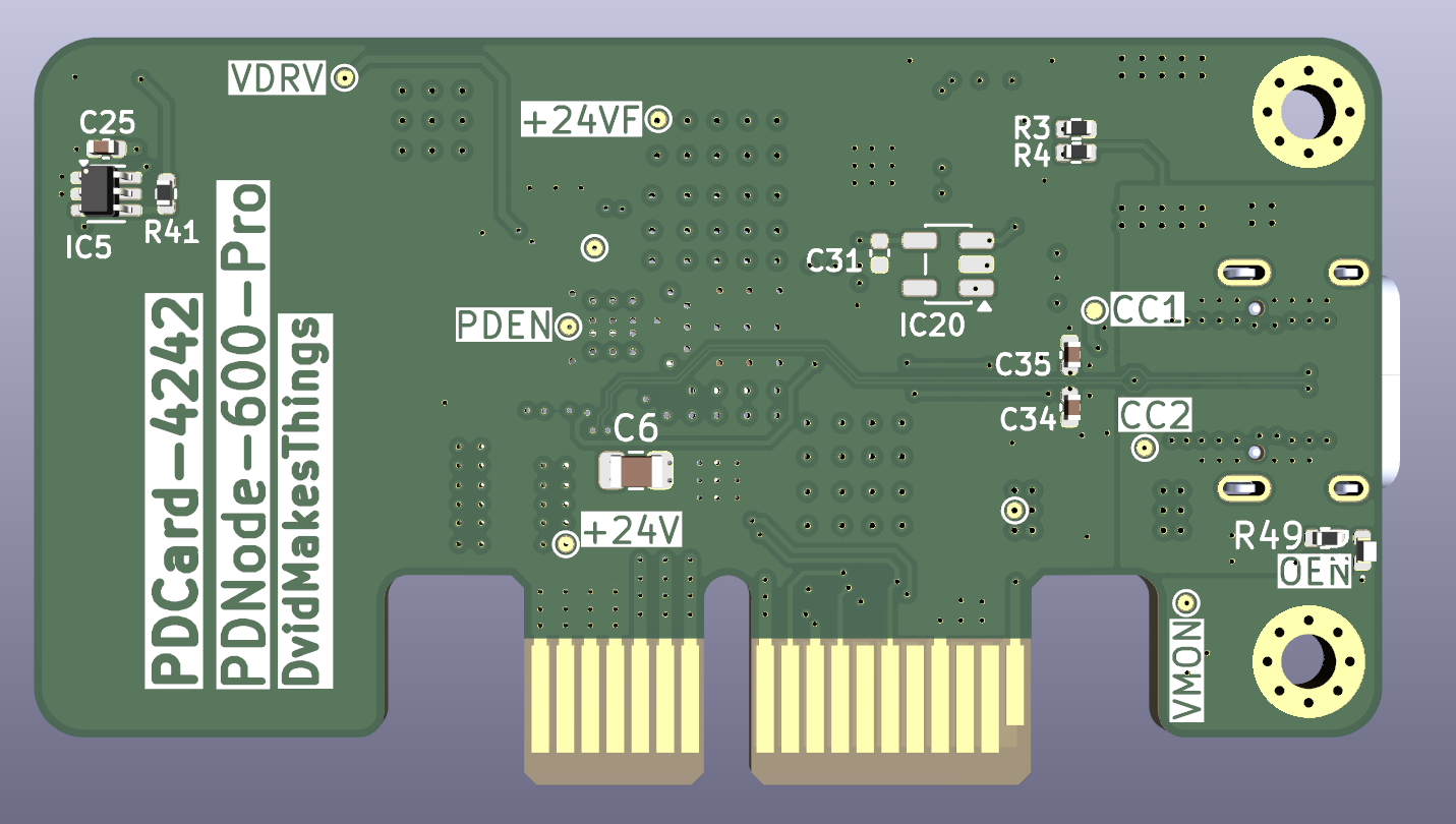
  • PDCard power stage (MPQ4242-AEC1)
  • Baseboard: Per-slot I2C muxing (TCA9548A)
  • Optional per-card EEPROM (not used, but capable)
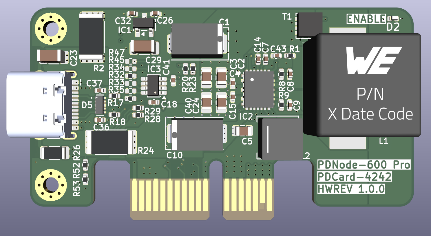
PDCard 3D Top View
PDCard Top
PDCard 3D Bottom View
PDCard Bottom
BladeCore-M54E Top View
BladeCore-M54E Top
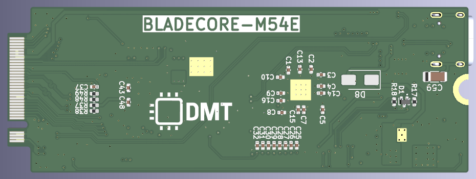
BladeCore-M54E Bottom View
BladeCore-M54E Bottom
BaseBoard 3D Top View
BladeCore-M54E Top
BaseBoard 3D Bottom View
BladeCore-M54E Bottom

License

Software Components

This project's software is licensed under the GNU Affero General Public License v3.0 (AGPL-3.0). See the Software License file for details.

What AGPL-3.0 means:
  • ✅ You can freely use, modify, and distribute this software

  • ✅ You can use this project for personal, educational, or internal purposes

  • ✅ You can contribute improvements back to this project

  • ⚠️ You must share any modifications you make if you distribute the software

  • ⚠️ You must release the source code if you run a modified version on a server that others interact with

  • ⚠️ You must keep all copyright notices intact

  • ❌ You cannot incorporate this code into proprietary software without sharing your source code

  • ❌ You cannot use this project in a commercial product without either complying with AGPL or obtaining a different license

Hardware Components

Hardware designs, schematics, and related documentation are licensed under the Creative Commons Attribution-NonCommercial-ShareAlike 4.0 International License (CC BY-NC-SA 4.0 International License). See the Hardware License file for details.

What CC BY-NC-SA 4.0 means:
  • ✅ You can study, modify, and distribute the hardware designs

  • ✅ You can create derivative works for personal, educational, or non-commercial use

  • ✅ You can build this project for your own personal use

  • ⚠️ You must give appropriate credit and indicate if changes were made

  • ⚠️ You must share any modifications under the same license terms

  • ⚠️ You must include the original license and copyright notices

  • ❌ You cannot use the designs for commercial purposes without explicit permission

  • ❌ You cannot manufacture and sell products based on these designs without a commercial license

  • ❌ You cannot create closed-source derivatives for commercial purposes

  • ❌ You cannot use the designer's trademarks without permission

Commercial & Enterprise Use

Commercial use of this project is prohibited without obtaining a separate commercial license. If you are interested in:

  • Manufacturing and selling products based on these designs
  • Incorporating these designs into commercial products
  • Any other commercial applications

Please contact me through any of the channels listed in the Contact section to discuss commercial licensing arrangements. Commercial licenses are available with reasonable terms to support ongoing development.

Contact

For questions or feedback:

Contributing

Contributions are welcome! As this is an early-stage project, please reach out before making substantial changes:

  1. Fork the repository
  2. Create a feature branch (git checkout -b feature/concept)
  3. Commit your changes (git commit -m 'Add concept')
  4. Push to the branch (git push origin feature/concept)
  5. Open a Pull Request with a detailed description

Parts

236
QtyValueFootprintReferences
36100nF 50VDS_Capacitor:C_0402_1005MetricC14, C15, C16, C17, C19, C24, C25, C26, C27, C28, C29, C30, C31, C32, C33, C34 +20
2010K 1%DS_Resistor:R_0402_1005MetricR2, R10, R11, R12, R13, R14, R15, R16, R17, R18, R19, R48, R49, R50, R51, R52 +4
12SN74LVC1G97QDCKRQ1DS_Peripherals:SOT-363_SC-70-6IC5, IC6, IC7, IC8, IC10, IC11, IC12, IC13, IC21, IC23, IC25, IC26
10100R 1%DS_Resistor:R_0402_1005MetricR75, R79, R80, R81, R84, R87, R88, R89, R94, R95
910uF 50VDS_Capacitor:C_0805_2012MetricC2, C3, C4, C5, C6, C38, C43, C47, C52
91K 1%DS_Resistor:R_0402_1005MetricR24, R74, R77, R82, R83, R90, R91, R92, R93
94.7K 1%DS_Resistor:R_0402_1005MetricR41, R56, R57, R61, R63, R65, R68, R71, R72
810018784-10200TLFDS_Connector:AMPHENOL_10018784-10210TLFJ4, J5, J6, J7, J8, J9, J10, J11
8Conn_01x02Connector_PinHeader_1.27mm:PinHeader_1x02_P1.27mm_VerticalJ14, J15, J16, J17, J18, J19, J20, J21
8SolderJumper_3_OpenJumper:SolderJumper-3_P1.3mm_Open_Pad1.0x1.5mmJP1, JP2, JP3, JP4, JP5, JP6, JP7, JP8
633R 1%DS_Resistor:R_0402_1005MetricR44, R45, R76, R78, R85, R86
52.2K 5%DS_Resistor:R_Array_Convex_4x0603R25, R26, R27, R28, R31
5MCP23017T-E/MLDS_Peripherals:QFN-28-1EP_6x6mm_P0.65mm_EP4.25x4.25mm_ThermalViasIC9, IC14, IC15, IC16, IC27
5MountingHole_PadMountingHole:MountingHole_3.2mm_M3_Pad_ViaH1, H2, H3, H4, H5
40.02R 1%DS_Resistor:R_1206_3216MetricR58, R59, R66, R67
4100R 1%DS_Resistor:R_Array_Convex_4x0603R42, R43, R46, R47
4100uF 25VDS_Capacitor:C_Elec_6.3x7.7C37, C41, C46, C51
410nF 50VDS_Capacitor:C_0402_1005MetricC54, C57, C59, C61
41M 1%DS_Resistor:R_1206_3216MetricR1, R23, R62, R70
41nF 2kVDS_Capacitor:C_1206_3216MetricC1, C23, C42, C49
433.2K 1%DS_Resistor:R_0402_1005MetricR60, R64, R69, R73
4AP22653W6-7DS_Peripherals:SOT-23-6IC17, IC18, IC19, IC20
4Red-GreenDS_Opto:LED_0605-1613D6, D7, D8, D9
34.7uF 25VDS_Capacitor:C_0402_1005MetricC18, C20, C21
35.1K 1%DS_Resistor:R_0402_1005MetricR21, R22, R30
22.2R 1%DS_Resistor:R_0402_1005MetricR3, R4
22.2uF 25VDS_Capacitor:C_0402_1005MetricC12, C13
2330uF 6.3VDS_Capacitor:2917C10, C11
251K 1%DS_Resistor:R_0402_1005MetricR8, R29
2AF SS-JB17.6DS_Connector:USB_A_Horizontal_StackedJ12, J13
2BAT54SDS_Diode:SOT23-3D1, D2
2FDMC7672DS_FET:DFN8_3x3T3, T4
2FDMC7692DS_FET:DFN8_3x3T1, T2
2PAC1720-1-AIA-TRDS_Peripherals:DFN-10-1EP_3x3mm_P0.5mm_EP1.58x2.35mm_ThermalViasIC22, IC24
10525592052DS_Connector:CON_525592052_MOLJ23
10ATO030.VPDS_Fuse:178.6165.0001-LittelfuseF1
115.4K 1%DS_Resistor:R_0402_1005MetricR5
11724470208DS_Connector:MOLEX_1724470208J22
12.2uH 9.5ADS_Inductor:7x6.6mmL1
13.3uH 13ADS_Inductor:7x6.6mmL2
1330uF 50VDS_Capacitor:CP_Elec_10x10.5C67
1470uF 4VDS_Capacitor:2917C9
147K 1%DS_Resistor:R_0402_1005MetricR9
16.57K 0.1%DS_Resistor:R_0402_1005MetricR6
1BlueDS_Opto:LED_0402_1005MetricD5
1CD74HC4067QRGYRQ1DS_Peripherals:Texas_RGY_R-PVQFN-N24_EP2.05x3.1mm_ThermalViasIC2
1J1B1211CCDDS_Connector:J1B1211CCDJ1
1M2.5DS_Test:Round Standoff Threaded M2.5 SteelST1
1MDT580M01001DS_Connector:BladeCore-M54E-5.8mmJ2
1SP0503BAHTGDS_Diode:SOT143D4
1TCA9548ARGERDS_Peripherals:Texas_RGE0024C_VQFN-24-1EP_4x4mm_P0.5mm_EP2.1x2.1mmIC4
1TPD4EUSB30DQARDS_Diode:USON10_2.5x1D3
1TPS51225CRUKRDS_Vreg:QFN20-3x3IC1
1USB-TYPE-C-018DS_Connector:USB_C_Receptacle_HCTL_HC-TYPE-C-16P-01AJ3

The 230 most common of 236 parts.

More from DvidMakesThings/HW_PDNode-600-Pro

3
  • 6 layers29 × 80.6 mmBladeCore M54E, the printed circuit board in 3D

    BladeCore M54E

    DvidMakesThings/HW_PDNode-600-Pro

    The PDNode-600 is a professional-grade, 600W USB Power Delivery Unit designed specifically for compact 10-inch rack systems, targeting embedded developers, homelab enthusiasts, test benches, and smart infrastructure.

    150 parts86AGPL-3.0
  • 6 layers53.9 × 35.5 mmPDNode PDCard-5031, the printed circuit board in 3D

    PDNode PDCard-5031

    DvidMakesThings/HW_PDNode-600-Pro

    The PDNode-600 is a professional-grade, 600W USB Power Delivery Unit designed specifically for compact 10-inch rack systems, targeting embedded developers, homelab enthusiasts, test benches, and smart infrastructure.

    125 parts86AGPL-3.0
  • 6 layers57.2 × 29.9 mmPDNode PDCard-4242, the printed circuit board in 3D

    PDNode PDCard-4242

    DvidMakesThings/HW_PDNode-600-Pro

    The PDNode-600 is a professional-grade, 600W USB Power Delivery Unit designed specifically for compact 10-inch rack systems, targeting embedded developers, homelab enthusiasts, test benches, and smart infrastructure.

    80 parts86AGPL-3.0

Similar boards

  • 4 layers191.2 × 190.9 mmNeptune, the printed circuit board in 3D

    Neptune

    Board-Folk/Neptune

    Recreation of the cancelled Sega console that combines Mega Drive/Genesis with 32X.

    379 parts180
  • 4 layers64 × 64 mmEspion cam, the printed circuit board in 3D

    Espion cam

    azais-corentin/espion

    Multi-camera IR marker tracking: ESP32-P4/C5 firmware, Rust host, KiCad hardware

    188 partsApache-2.0
  • 4 layers54.3 × 39.1 mmMaru alpha, the printed circuit board in 3D

    Maru alpha

    prs2026/Lyra-flight-computer

    repo for the lyra flight computer

    99 parts3GPL-3.0
  • 8 layers100.2 × 55 mmJetson nano baseboard, the printed circuit board in 3D

    Jetson nano baseboard

    antmicro/jetson-nano-baseboard

    Antmicro's open hardware baseboard for the NVIDIA Jetson Nano, TX2 NX and Xavier NX

    391 parts548Apache-2.0
  • 4 layers128.5 × 40 mmScalenode cm4-baseboard, the printed circuit board in 3D

    Scalenode cm4-baseboard

    antmicro/scalenode-cm4-baseboard

    Baseboard for Raspberry Pi 4 Compute Module optimized for clustering

    146 parts152Apache-2.0
  • 6 layers100 × 70 mmSa800u baseboard hw, the printed circuit board in 3D

    Sa800u baseboard hw

    antmicro/snapdragon-845-baseboard

    https://antmicro.com/blog/2022/04/open-source-snapdragon-845-baseboard/

    616 parts70Apache-2.0
  • 2 layers15 × 10 mmMagnetic switch, the printed circuit board in 3D

    Magnetic switch

    miket6000/SimpleSwitch

    A magnetic power switch for use in rocketry

    20 parts1CERN-OHL-W-2.0

Questions

How big is the PDNode Baseboard PCB?

It measures 203 × 151.8 mm and has 6 copper layers, 1.56 mm thick.

What parts does the PDNode Baseboard use?

236 parts, built around the PAC1720-1-AIA-TR, TCA9548ARGER, TPS51225CRUKR and SN74LVC1G97QDCKRQ1. The full list of its parts is on this page, with links to each part's symbol and footprint where PCBKit's library has them.

Where can I download the PDNode Baseboard KiCad files?

From the DvidMakesThings/HW_PDNode-600-Pro repository on GitHub, at the commit this page was made from: the board is src/HardwareDesign/1.0.0/PDNode-600_Pro_Baseboard_100/PDNode_Baseboard.kicad_pcb and its schematic src/HardwareDesign/1.0.0/BladeCore-M54_100/BladeCore-M54E.kicad_sch. PCBKit opens the board in the browser, with nothing to install.

Can I use the PDNode Baseboard design in my own project?

Its repository publishes it under the AGPL-3.0 licence: you may reuse it on that licence's terms (keep the author's notice, and for a copyleft licence share your changes alike).