4 layers63.5 × 40.6 mm

 souptik-samanta/Hackducky13
Our board is powered by the reliable Raspberry Pi RP2040 microcontroller and includes 16 MB of flash storage, giving plenty of room for scripts and firmware.
Hackducky is an open-source printed circuit board by souptik-samanta, from the souptik-samanta/Hackducky repository on GitHub. It is a 4-layer board of 52.3 × 25.3 mm with 83 parts on 70 nets, routed with 773 tracks and 198 vias.
It is built around the RP2040, W25Q128JVSIQ and SRV05-4, with the AMS1117-3.3 among its other parts. Its parts include 20 capacitors, 18 resistors, 6 diodes, 6 connectors and 5 ICs. It belongs with the RP2040 boards of this library.


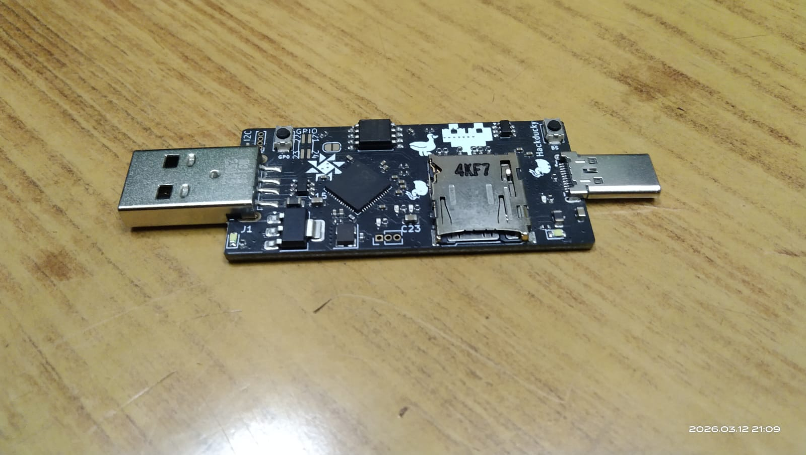
HackDucky is a compact USB automation and security testing device designed in a small portable form factor. It is inspired by keystroke-injection tools and can emulate a USB keyboard to execute scripted commands automatically when plugged into a computer.The device is powered by a rp2040 and supports payload scripting, making it useful for automation, demonstrations, and authorized penetration testing.
Below is the render of the HackDucky board.
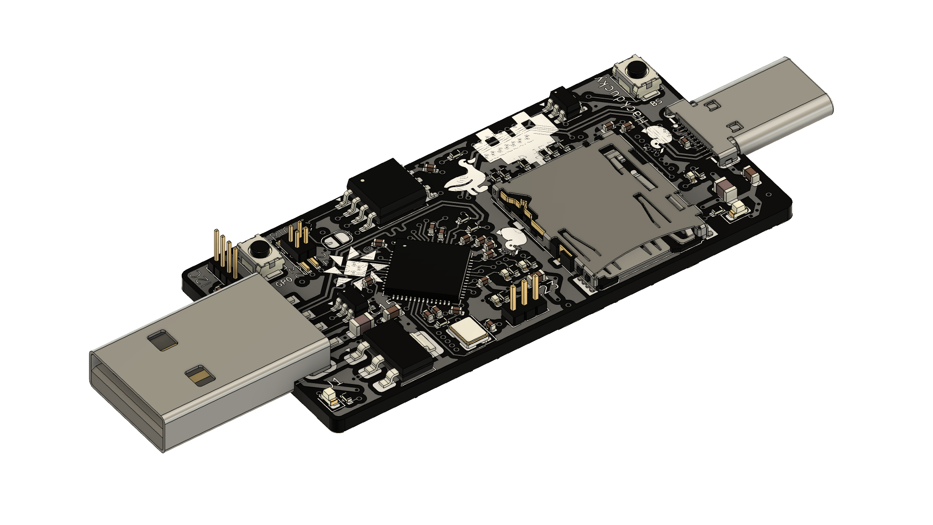
Most devices designed for USB automation or security testing are either expensive, closed-source, or difficult for beginners to modify. We wanted to build something compact, affordable, and easy to experiment with while still being powerful enough for real projects. HackDucky aims to provide a small, portable platform for USB automation, inspired by devices used in security research such as USB Rubber Ducky and other BadUSB-style tools.
Our board is powered by the reliable Raspberry Pi RP2040 microcontroller and includes 16 MB of flash storage, giving plenty of room for scripts and firmware. It also features an SD card slot, allowing users to store and switch between multiple payloads or automation scripts easily. This makes the device flexible for experimentation, demos, and authorized security testing.
HackDucky is designed for a wide range of users. Students can explore how USB HID devices work and learn about hardware security concepts. Makers can use it as a programmable USB automation tool for repetitive tasks. Security enthusiasts can experiment with BadUSB-style techniques in controlled environments, while developers can modify the firmware and hardware to create their own custom tools.
Your HackDucky ships without firmware preinstalled, so you need to flash it before using the board.
.uf2 firmware file..uf2 file onto the drive.After flashing, a new drive named CIRCUITPY should appear.
git clone https://github.com/hackclub/hackduckyOpen the repository and navigate to the firmware directory.
Copy all files from the firmware folder to the CIRCUITPY drive.
Replace existing files if prompted.
Delete the existing code.py file.
Open the ducks folder on the HackDucky drive.
Delete any existing files in the folder.
Copy your script into the folder with the .ducky extension.
Your HackDucky is now ready to run scripts.
Enjoy ¯\_(ツ)_/¯Email Souptik at me@souptik.me(me[at]souptik[dot]me)
| Qty | Value | Footprint | References |
|---|---|---|---|
| 12 | TestPoint | TestPoint:TestPoint_Pad_D1.0mm | TP1, TP2, TP3, TP4, TP5, TP6, TP7, TP8, TP9, TP10, TP11, TP12 |
| 11 | 100nF | Capacitor_SMD:C_0402_1005Metric | C7, C8, C11, C17, C18, C19, C20, C21, C22, C24, C25 |
| 10 | LOGO | LOGO | G***, G***, G***, G***, G***, G***, G***, G***, G***, G*** |
| 6 | 10k | Resistor_SMD:R_0402_1005Metric | R16, R17, R18, R19, R20, R21 |
| 4 | 220 | Resistor_SMD:R_0402_1005Metric | R3, R5, R6, R10 |
| 4 | LED | LED_SMD:LED_0402_1005Metric | D1, D2, D3, D4 |
| 3 | 1uF | Capacitor_SMD:C_0402_1005Metric | C1, C9, C10 |
| 3 | 22uF | Capacitor_SMD:C_0603_1608Metric | C14, C15, C23 |
| 2 | 120ohm.100Mhz | Inductor_SMD:L_0805_2012Metric | FB1, FB2 |
| 2 | 15pF | Capacitor_SMD:C_0402_1005Metric | C12, C13 |
| 2 | 1k | Resistor_SMD:R_0402_1005Metric | R8, R9 |
| 2 | 27.4 | Resistor_SMD:R_0402_1005Metric | R7, R22 |
| 2 | LED | LED_SMD:LED_0603_1608Metric | D5, D6 |
| 2 | R | Resistor_SMD:R_0402_1005Metric | R1, R2 |
| 2 | SRV05-4 | Package_TO_SOT_SMD:SOT-23-6 | U5, U6 |
| 1 | 100n | Capacitor_SMD:C_0402_1005Metric | C16 |
| 1 | 5.1K | Capacitor_SMD:C_0402_1005Metric | R4 |
| 1 | AMS1117-3.3 | Package_TO_SOT_SMD:SOT-223-3_TabPin2 | U2 |
| 1 | BOOT_SEL | Button_Switch_SMD:SW_Push_SPST_NO_Alps_SKRK | SW3 |
| 1 | Conn_01x03_Pin | Connector_PinHeader_1.27mm:PinHeader_1x03_P1.27mm_Vertical | J4 |
| 1 | Conn_01x04_Pin | Connector_PinHeader_1.00mm:PinHeader_1x04_P1.00mm_Vertical | J6 |
| 1 | Conn_02x02_Top_Bottom | Connector_PinHeader_1.00mm:PinHeader_2x02_P1.00mm_Vertical_SMD | J2 |
| 1 | Crystal_GND24 | Crystal:Crystal_SMD_Abracon_ABM8G-4Pin_3.2x2.5mm | Y1 |
| 1 | DNF | Resistor_SMD:R_0402_1005Metric | R15 |
| 1 | GP0 | Button_Switch_SMD:SW_Push_SPST_NO_Alps_SKRK | SW4 |
| 1 | Jumper_2_Open | Jumper:SolderJumper-2_P1.3mm_Open_RoundedPad1.0x1.5mm | JP1 |
| 1 | Micro_SD_Card | Connector_Card:microSD_HC_Hirose_DM3AT-SF-PEJM5 | J3 |
| 1 | RP2040 | Package_DFN_QFN:QFN-56-1EP_7x7mm_P0.4mm_EP3.2x3.2mm | U4 |
| 1 | USB_A | Connector_USB:USB_A_CNCTech_1001-011-01101_Horizontal | J1 |
| 1 | USB_C_Plug | RASPBERRY_PI_PICO:USB-C-SMD_U261-121N-4BS2S | P2 |
| 1 | W25Q128JVS | Package_SO:SOIC-8_5.3x5.3mm_P1.27mm | U3 |


khill25/Dreamdrive
Open source Retro Rom Carts and ODEs by Dreamcraft Industries


minipadKB/minipad
The PCB and case files for the minipad, an RP2040-based 2-3-key keypad for the rhythm game osu!.

ScatteredDrifter/Buran-Ortho
A 39-key orthogonal keyboard with support for two knobs, based on a rp2040


It measures 52.3 × 25.3 mm and has 4 copper layers, 1.6 mm thick.
83 parts, built around the RP2040, W25Q128JVSIQ, SRV05-4 and AMS1117-3.3. The full list of its parts is on this page, with links to each part's symbol and footprint where PCBKit's library has them.
From the souptik-samanta/Hackducky repository on GitHub, at the commit this page was made from: the board is Pcb/hackducky.kicad_pcb and its schematic Pcb/hackducky.kicad_sch. PCBKit opens the board in the browser, with nothing to install.
Its repository states no licence, so its author keeps all rights: ask souptik-samanta before reusing the design.