4 layers52.3 × 25.3 mm
Hackducky
souptik-samanta/Hackducky
Our board is powered by the reliable Raspberry Pi RP2040 microcontroller and includes 16 MB of flash storage, giving plenty of room for scripts and firmware.
83 parts13

 kevinjuszczyk/ice204012
ice40 + RP2040 combo
Ice2040 is an open-source printed circuit board by kevinjuszczyk, from the kevinjuszczyk/ice2040 repository on GitHub. It is a 4-layer board of 63.5 × 40.6 mm with 124 parts on 135 nets, routed with 1,875 tracks and 163 vias.
It is built around the RP2040, W25Q128JVSIQ and AMS1117-3.3, with the SRV05-4 among its other parts. Its parts include 74 resistors, 24 capacitors, 12 connectors, 5 ICs and 2 diodes. It belongs with the fPGA and programmable logic boards and the RP2040 and FPGA and CPLD boards of this library.


ICE40UP5K FPGA + RP2040 Hacker Board
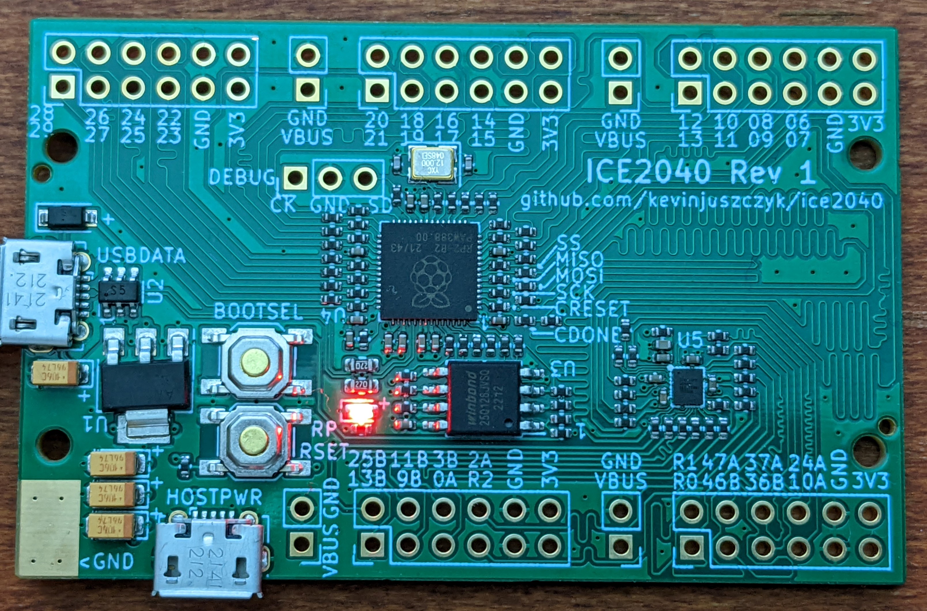
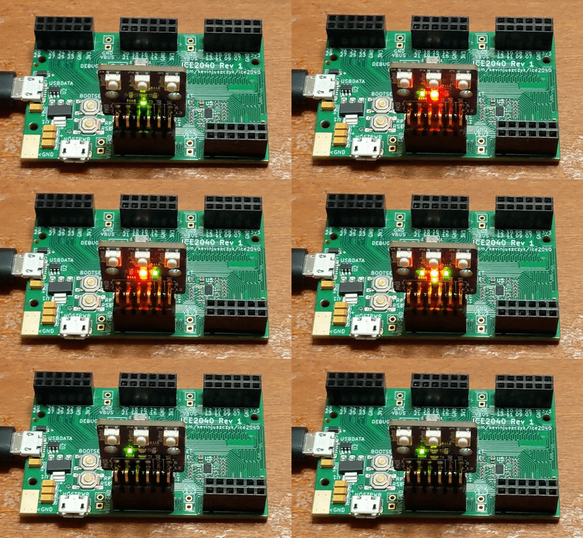
The ICE2040 combines a Lattice ICE40UP5K FPGA with a Raspberry Pi RP2040. The RP2040 is used to configure the ICE40 SRAM, and optionally provide a clock or host communication. Pmod connectors are provided for both the ICE40 and RP2040, with the rightmost connectors lined up in such a way that up to 16 additional lines between the ICE40 and RP2040 can be bridged together using a PCB or ribbon cable.
A friend expressed an interest in implementing a RISC-V processor using an FPGA, something like learn-fpga. Due to the ongoing parts shortage, many of the low-end FPGA dev boards are either out of stock, or have moved out of the pocket change price range. With an eye toward building a board using whatever might still be in stock, I found that the major retailers have many thousands of ICE40 parts in fine pitch BGA packages. I started playing around in KiCad with the ICE40UP5K-UWG30 (30-ball 0.4mm pitch) part to see if there was a way to fan out enough of the pins to make a reasonably useful board. By modifying the shape of the pads, I was able to achieve a complete fanout that can be fabricated with JLCPCB's 4-layer process. Most boards like this use an FTDI serial converter for host communication and FPGA configuration, but these have also been hard to get. I decided to use an RP2040 for these functions, since they are in stock and much less expensive.
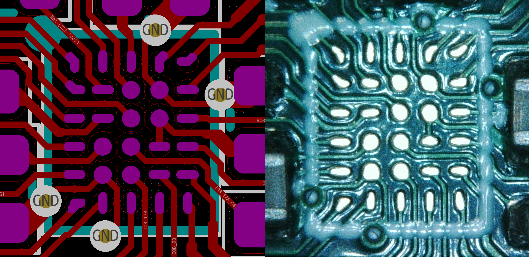
The board can be fabricated using JLCPCB's 4-layer process, and all components assembled (except for the ICE40 and Pmod headers) using their Economic PCBA service. Jlcfab.zip contains the fabrication files including the BOM, footprint position, drill, and Gerber files. Jlcboardsettings.txt shows how to configure the JLCPCB order screen. Note that you want to specify the technical review (Confirm Production Files) for both the board fabrication and assembly. This will let JLCPCB adjust the board traces and parts orientation as needed.
NOTE: If you haven't soldered BGA packages before, this is not a good one to start with.
| Qty | Value | Footprint | References |
|---|---|---|---|
| 58 | 33 | Resistor_SMD:R_0402_1005Metric | R10, R11, R12, R21, R22, R23, R24, R25, R26, R27, R28, R29, R30, R31, R32, R33 +42 |
| 17 | 1u | Capacitor_SMD:C_0402_1005Metric | C7, C8, C10, C11, C12, C13, C14, C15, C16, C17, C18, C19, C20, C21, C22, C23 +1 |
| 8 | 10k | Resistor_SMD:R_0402_1005Metric | R2, R4, R13, R14, R15, R16, R17, R67 |
| 5 | PMOD_HOST | kmj_custom:PMOD_HOST | J8, J9, J10, J11, J12 |
| 4 | 10u | Capacitor_Tantalum_SMD:CP_EIA-3216-18_Kemet-A | C1, C2, C3, C4 |
| 4 | 1x02_P2.54 | Connector_PinHeader_2.54mm:PinHeader_1x02_P2.54mm_Vertical | J3, J4, J5, J6 |
| 4 | M2_MountingHole | MountingHole:MountingHole_2.2mm_M2_ISO7380 | H1, H2, H3, H4 |
| 3 | 1k | Resistor_SMD:R_0402_1005Metric | R1, R3, R5 |
| 2 | 15p | Capacitor_SMD:C_0402_1005Metric | C5, C6 |
| 2 | 27 | Resistor_SMD:R_0603_1608Metric | R19, R20 |
| 2 | SW_Push | Button_Switch_SMD:SW_SPST_SKQG_WithoutStem | SW1, SW2 |
| 2 | USB_Micro_B | Connector_USB:USB_Micro-B_Molex-105017-0001 | J1, J2 |
| 1 | 100 | Resistor_SMD:R_0402_1005Metric | R74 |
| 1 | 10u | Capacitor_SMD:C_0402_1005Metric | C24 |
| 1 | 12M | Crystal:Crystal_SMD_SeikoEpson_FA238-4Pin_3.2x2.5mm | Y1 |
| 1 | 1N5819 | Diode_SMD:D_SOD-123 | D1 |
| 1 | 1x03_P2.54 | Connector_PinHeader_2.54mm:PinHeader_1x03_P2.54mm_Vertical | J7 |
| 1 | 2.2k | Resistor_SMD:R_0402_1005Metric | R73 |
| 1 | 200 | Resistor_SMD:R_0402_1005Metric | R18 |
| 1 | AMS1117-3.3 | Package_TO_SOT_SMD:SOT-223-3_TabPin2 | U1 |
| 1 | LED | Diode_SMD:D_0603_1608Metric | D2 |
| 1 | RP2040 | kmj_custom:QFN-56-1EP_7x7mm_P0.4mm_EP3.2x3.2mm_MoreThermalVias | U4 |
| 1 | SRV05-4 | Package_TO_SOT_SMD:SOT-23-6 | U2 |
| 1 | W25Q128JVS | Package_SO:SOIC-8_5.23x5.23mm_P1.27mm | U3 |
| 1 | iCE40UP-30 | kmj_custom:BGA-30_5x6_2.114x2.537mm | U5 |
souptik-samanta/Hackducky
Our board is powered by the reliable Raspberry Pi RP2040 microcontroller and includes 16 MB of flash storage, giving plenty of room for scripts and firmware.


khill25/Dreamdrive
Open source Retro Rom Carts and ODEs by Dreamcraft Industries


minipadKB/minipad
The PCB and case files for the minipad, an RP2040-based 2-3-key keypad for the rhythm game osu!.

ScatteredDrifter/Buran-Ortho
A 39-key orthogonal keyboard with support for two knobs, based on a rp2040


It measures 63.5 × 40.6 mm and has 4 copper layers, 1.58 mm thick.
124 parts, built around the RP2040, W25Q128JVSIQ, AMS1117-3.3 and SRV05-4. The full list of its parts is on this page, with links to each part's symbol and footprint where PCBKit's library has them.
From the kevinjuszczyk/ice2040 repository on GitHub, at the commit this page was made from: the board is kicad/ice2040.kicad_pcb and its schematic kicad/ice2040.kicad_sch. PCBKit opens the board in the browser, with nothing to install.
Its repository states no licence, so its author keeps all rights: ask kevinjuszczyk before reusing the design.