4 layers73 × 50 mm
Tardigrade
nortismo/tardigrade
Open Hardware board with an embedded LPC55 MCU and a SX1262 LoRa transceiver
127 parts

 SorenGilkeyJohnson/LowLoRa3
A solar powered, batteryless LoRa (expandable) sensor node powered from a supercapacitor charged by a small solar cell using an energy harvester.
Low Power LoRa is an open-source printed circuit board by SorenGilkeyJohnson, from the SorenGilkeyJohnson/LowLoRa repository on GitHub, published under the CERN-OHL-S-2.0 licence. It is a 4-layer board of 23.4 × 25.4 mm with 70 parts on 57 nets, routed with 346 tracks and 89 vias.
It is built around the PE4259-63, SX1262IMLTRT and KXOB121K04F-TR, with the LPS22HB, BQ25504RGT and SI2301CDS among its other parts. Its parts include 29 capacitors, 17 resistors, 8 inductors, 6 ICs and 3 connectors. It belongs with the radio and wireless and power boards of this library.


A solar powered, batteryless LoRa (expandable) sensor node powered from a supercapacitor charged by a small solar cell using an energy harvester. This was built around the Semtech SX1262 LoRa transceiver (US band; 915 MHz) and the low power MSPM0L110x MCU (TI; M0+), this board is a monitoring platform for anything you might want! The board is made around the solar cell and is roughly 23x24mm.
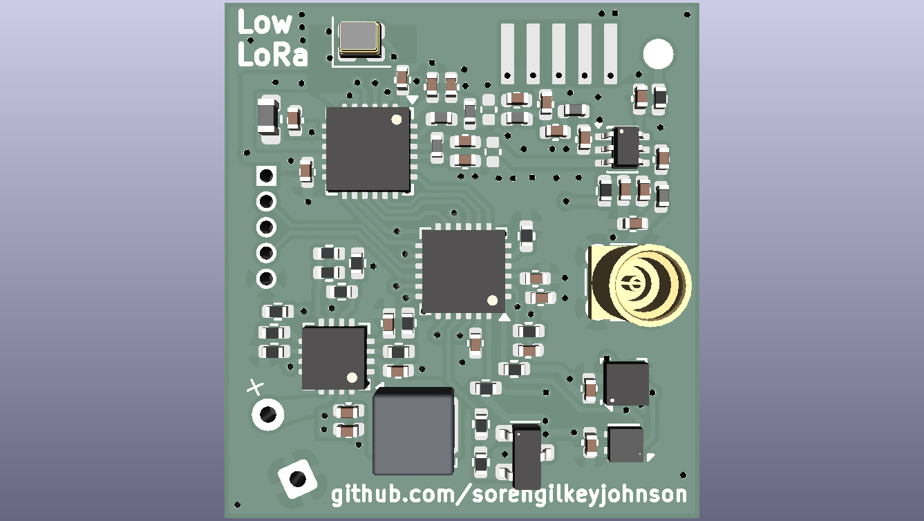
When researching this concept, I had found a few previous examples of this being done (e.g. nootropicdesign). I had not found an example, however, of a board that was fully self contained. When I was researching the component selection I really wanted it to be fully on board, which drove my decision to use a supercapacitor over a traditional Li-ION cell (almost none are SMD) and made me want to use a chip or PCB antenna. I found a supercapacitor that should work (this is my first time working with them), but I did not have enough room for an onboard antenna. Because of this I decided to add an external antenna through a connector. Another reason for this is the solar cell can block the RF waves from propagating properly. My project is still fairly unique from any existing solution, because I have found that it is rare to use a SMD solar cell. This is one of the biggest ones available on the market, as most are designed for handheld calculators. Figuring out the power budget was very difficult for this project, and that was probably the thing I spent the most time on. Thankfully, the SX1262 datasheet had detailed power budget options, and I was able to base it off of that (almost all of my battery consumption should be from that). This project taught me a lot about the importance of component selection! (I probably spent 2 times longer on this than any other project I had done vs the routing). When I get the board, I hope I can get it so that it is watertight. I have already done some research into gaskets for the humidity sensor (as this needs access to the outside world to get a good reading), but this seems pretty hard to do. There is a version of the sensor that has this built in, but it is far more expensive and is hard to get from most suppliers. I plan to use silicone around the PCB to protect the border of the solar cell from accidental damage, and put a piece of fiberglass over it. I made sure to keep all the parts that would petrude together, so I should have a slightly easier time designing the case. I hope I can get this board and test it out soon!
| Main Components | Part | Notes |
|---|---|---|
| LoRa Transceiver | SX1262 | Main IC, tuned for 915 MHz (US LoRa band) |
| Antenna | MMCX connector | External antenna due to PCB space constraints and having a metal backing (solar cell) |
| MCU | MSPM0L110x | I2C + SPI, wide voltage range, low cost, high availability from LCSC |
| Energy Harvester | BQ25504 | Manages charging from the solar cell and is very efficient. Gold standard for applications like this. |
| Solar Cell | KXOB121K04F-TR | very nice solar cell available on Digikey |
| Energy Storage | CXP-3R0335R-TW Supercapacitor | Low ESR; high capacitance; relatively space efficient |
| Load Switch | PMOS | Controlled by MCU to gate VSYS in order to save power for the rest of the system |
| Humidity/Temp Sensor | SHT4x | I2C |
| Pressure Sensor | LPS22HB | I2C |
| Antenna Switch | PE4259 | RF switch for the SX1262 (exact same component from reference design) |
| PCB Size | 23 mm x 25 mm | Large Solar Cell at a relatively high voltage compared to others on the market |
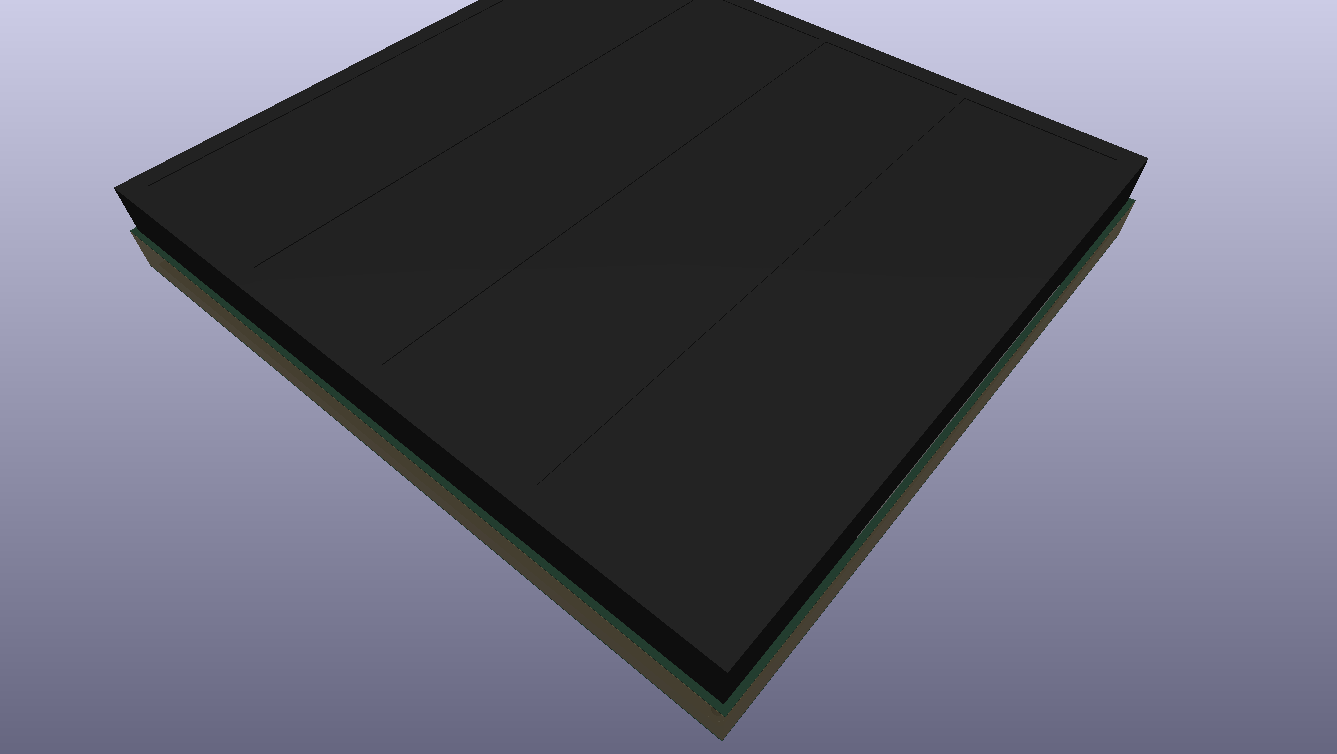
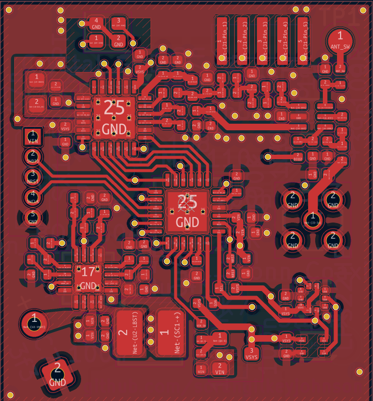
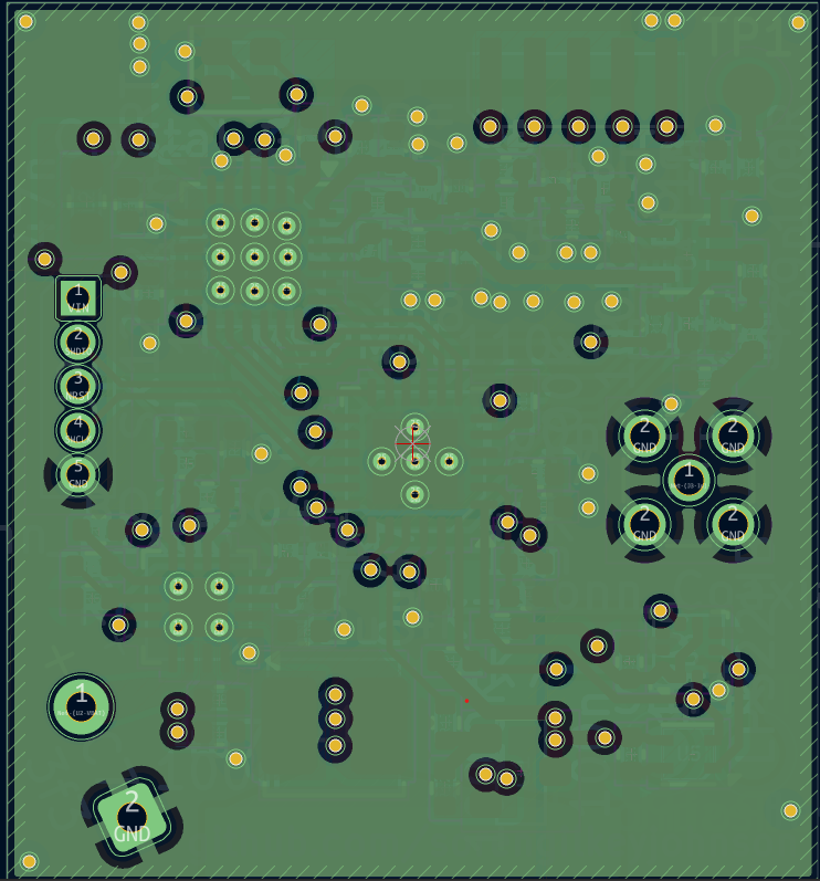
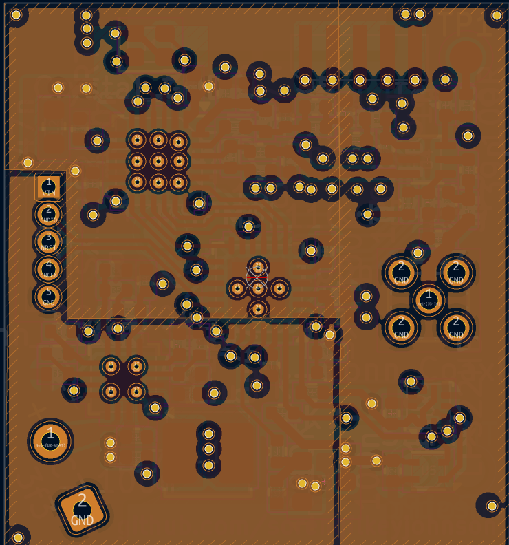
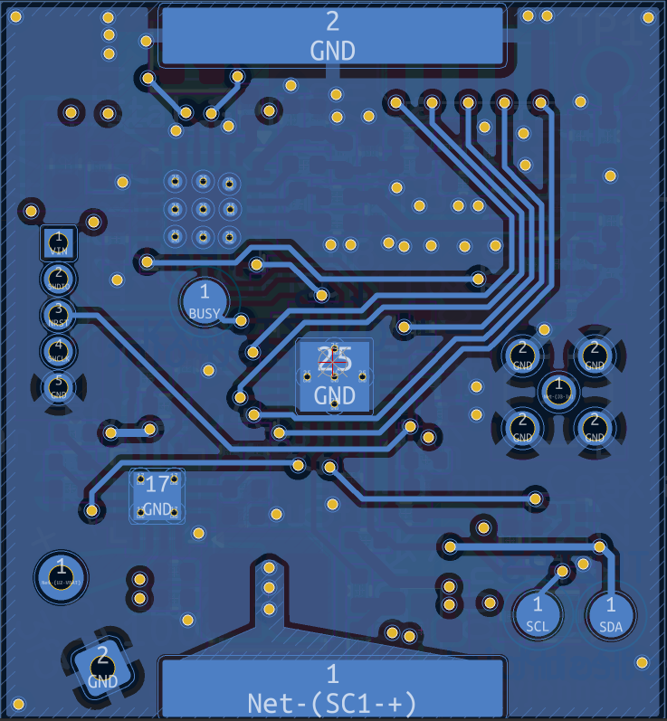
Schematic: Low Power LoRa Schematic.pdf
.
├── KiCAD/
│  ├── Low Power LoRa.kicad_pcb     # PCB layout
│  ├── Low Power LoRa.kicad_prl     # Project local settings
│  ├── Low Power LoRa.kicad_pro     # Project file
│  └── Low Power LoRa.kicad_sch     # Schematic
├── fabrication/
│  ├── bom.csv                      # Bill of materials
│  ├── gerbers.zip                  # Gerber files for PCB fabrication
│  └── pick_and_place.csv           # Pick-and-place file for assembly
├── images/
│  ├── Low Power LoRa Bottom View 3D.png
│  ├── Low Power LoRa Front View.png
│  ├── Low Power LoRa Layer 1.png
│  ├── Low Power LoRa Layer 2.png
│  ├── Low Power LoRa Layer 3.png
│  ├── Low Power LoRa Layer 4.png
│  └── Low Power LoRa Schematic.pdf
├── LICENSE
└── README.mdFabrication files can be found here: fabrication/ folder:
The BOM was generated using LCSC, so ignore the minimum part quantities (these get messed up due to MOQ). You should be able to use the KiCAD files to generate your own.
The MSPM0L110x is programmed with the SWD header. I do not have the board yet, so I will update this section more later when I have more information about real-world testing.
See LICENSE for details.
| Qty | Value | Footprint | References |
|---|---|---|---|
| 9 | R | Resistor_SMD:R_0402_1005Metric | R2, R3, R4, R5, R6, R7, R8, R9, R10 |
| 5 | 100n | Capacitor_SMD:C_0402_1005Metric | C3, C10, C11, C22, C29 |
| 4 | TestPoint | TestPoint:TestPoint_Pad_D1.5mm | TP1, TP2, TP3, TP4 |
| 3 | 4u7 | Capacitor_SMD:C_0402_1005Metric | C2, C6, C8 |
| 2 | 100K | Resistor_SMD:R_0402_1005Metric | R11, R12 |
| 2 | 100R | Resistor_SMD:R_0402_1005Metric | R16, R17 |
| 2 | 10n | Capacitor_SMD:C_0402_1005Metric | C1, C5 |
| 2 | 1n | Capacitor_SMD:C_0402_1005Metric | C24, C25 |
| 2 | 1p8 | Capacitor_SMD:C_0402_1005Metric | C14, C23 |
| 2 | 39p | Capacitor_SMD:C_0402_1005Metric | C21, C26 |
| 2 | 3p3 | Capacitor_SMD:C_0402_1005Metric | C27, C28 |
| 2 | 4K7 | Resistor_SMD:R_0402_1005Metric | R14, R15 |
| 2 | C | Capacitor_SMD:C_0402_1005Metric | C17, C18 |
| 1 | 0R | Inductor_SMD:L_0402_1005Metric | L3 |
| 1 | 0u47 | Capacitor_SMD:C_0402_1005Metric | C4 |
| 1 | 10K | Resistor_SMD:R_0402_1005Metric | R13 |
| 1 | 15n | Inductor_SMD:L_0402_1005Metric | L4 |
| 1 | 1u | Capacitor_SMD:C_0402_1005Metric | C9 |
| 1 | 22u | Inductor_SMD:L_Wuerth_LQFS-3818 | L1 |
| 1 | 2n5 | Inductor_SMD:L_0402_1005Metric | L6 |
| 1 | 2p4 | Capacitor_SMD:C_0402_1005Metric | C16 |
| 1 | 3f3 | Capacitor_THT:CP_Radial_D8.0mm_P3.50mm | C7 |
| 1 | 3p | Capacitor_SMD:C_0402_1005Metric | C19 |
| 1 | 470n | Capacitor_SMD:C_0402_1005Metric | C12 |
| 1 | 47K | Resistor_SMD:R_0402_1005Metric | R1 |
| 1 | 47n | Capacitor_SMD:C_0402_1005Metric | C13 |
| 1 | 47n | Inductor_SMD:L_0402_1005Metric | L5 |
| 1 | 47n | Inductor_SMD:L_0603_1608Metric | L2 |
| 1 | 47p | Capacitor_SMD:C_0402_1005Metric | C15 |
| 1 | 4n7 | Inductor_SMD:L_0402_1005Metric | L7 |
| 1 | 5p6 | Capacitor_SMD:C_0402_1005Metric | C20 |
| 1 | 9n1 | Inductor_SMD:L_0402_1005Metric | L8 |
| 1 | BQ25504 | Package_DFN_QFN:VQFN-16-1EP_3x3mm_P0.5mm_EP1.68x1.68mm_ThermalVias | U2 |
| 1 | Conn_01x05 | Connector_PinHeader_1.27mm:PinHeader_1x05_P1.27mm_Vertical | J2 |
| 1 | Conn_01x05 | Connector_PinHeader_1.27mm:PinHeader_1x05_P1.27mm_Vertical_SMD_Pin1Left | J1 |
| 1 | Conn_Coaxial | Connector_Coaxial:MMCX_Molex_73415-1471_Vertical | J3 |
| 1 | Crystal_GND24 | Crystal:Crystal_SMD_2016-4Pin_2.0x1.6mm | Y1 |
| 1 | KXOB121K04F-TR | Custom_Footprint_Purchase:KXOB121K04F-TR | SC1 |
| 1 | LPS22HB | Package_LGA:ST_HLGA-10_2x2mm_P0.5mm_LayoutBorder3x2y | U6 |
| 1 | MSPM0L110x | Package_DFN_QFN:VQFN-24-1EP_4x4mm_P0.5mm_EP2.45x2.45mm_ThermalVias | U1 |
| 1 | PE4259 | Package_TO_SOT_SMD:SOT-363_SC-70-6 | U4 |
| 1 | SHT4x | Sensor_Humidity:Sensirion_DFN-4_1.5x1.5mm_P0.8mm_SHT4x_NoCentralPad | U5 |
| 1 | SX1262IMLTRT | Package_DFN_QFN:QFN-24-1EP_4x4mm_P0.5mm_EP2.6x2.6mm | U3 |
| 1 | Si2301CDS | PCM_Package_TO_SOT_SMD_AKL:SOT-23 | Q1 |
It measures 23.4 × 25.4 mm and has 4 copper layers, 1.6 mm thick.
70 parts, built around the PE4259-63, SX1262IMLTRT, KXOB121K04F-TR and LPS22HB. The full list of its parts is on this page, with links to each part's symbol and footprint where PCBKit's library has them.
From the SorenGilkeyJohnson/LowLoRa repository on GitHub, at the commit this page was made from: the board is KiCAD/Low Power LoRa.kicad_pcb and its schematic KiCAD/Low Power LoRa.kicad_sch. PCBKit opens the board in the browser, with nothing to install.
Its repository publishes it under the CERN-OHL-S-2.0 licence: you may reuse it on that licence's terms (keep the author's notice, and for a copyleft licence share your changes alike).
nortismo/tardigrade
Open Hardware board with an embedded LPC55 MCU and a SX1262 LoRa transceiver

Horizon-Avionics/Horizon-H1
Building a fully open-source flight computer for amateur rocketry!

Space-and-Satellite-Systems-UC-Davis/PCBs
Collection of all the PCBs within SSS

knivier/SkyCell
The telecommunications solution on a balloon...for broke people alike.


