
4 layers40 × 40 mm

 sneakylizard123-4/FTDIboard
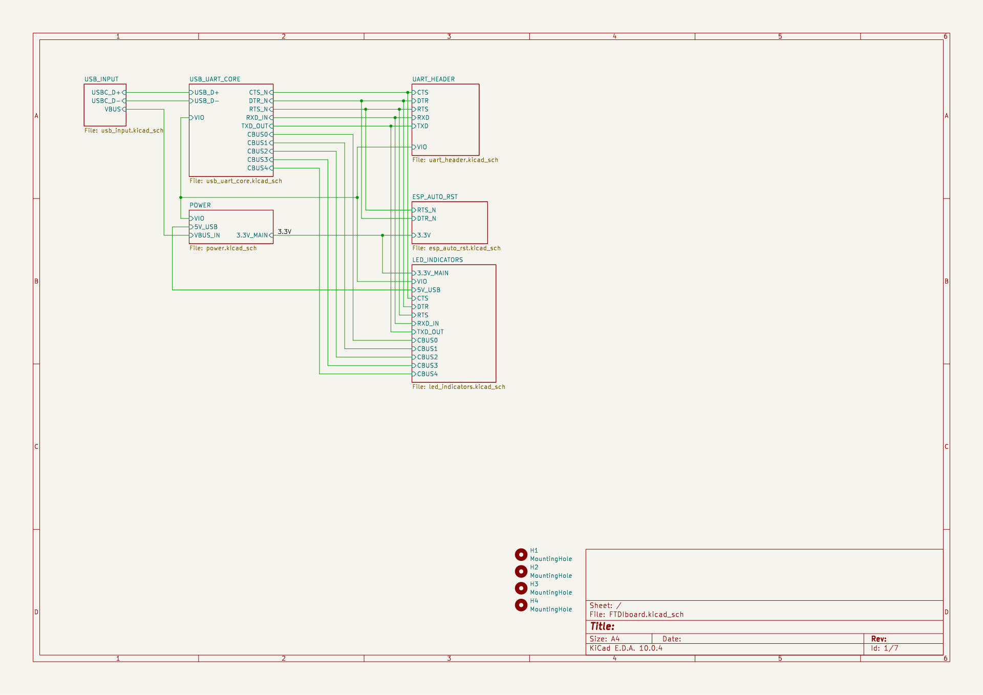
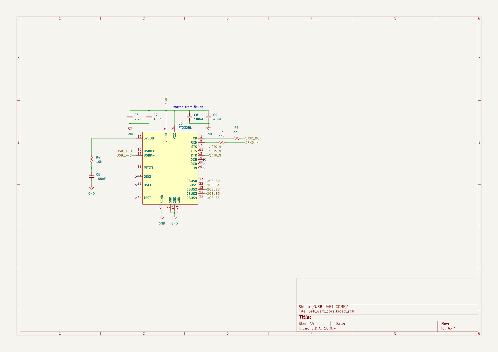
FTDIboard is a small USB-to-UART interface that uses the FT232RL and a switchable 3.3V/5V logic rail.
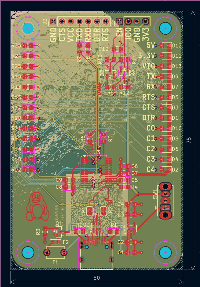
FTDIboard is an open-source printed circuit board by sneakylizard123-4, from the sneakylizard123-4/FTDIboard repository on GitHub. It is a 4-layer board of 50 × 75 mm with 69 parts on 56 nets, routed with 414 tracks and 79 vias.
It is built around the FT232RL, TLV75733PDBV and USBLC6-2SC6, with the BC817 and AO3401A among its other parts. Its parts include 25 resistors, 13 diodes, 10 capacitors, 3 ICs and 3 transistors.


FTDIboard is a small USB-to-UART interface that uses the FT232RL and a switchable 3.3V/5V logic rail.
| References | Qty | Value | Footprint |
|---|---|---|---|
| U3 | 1 | FT232RL | SSOP-28 |
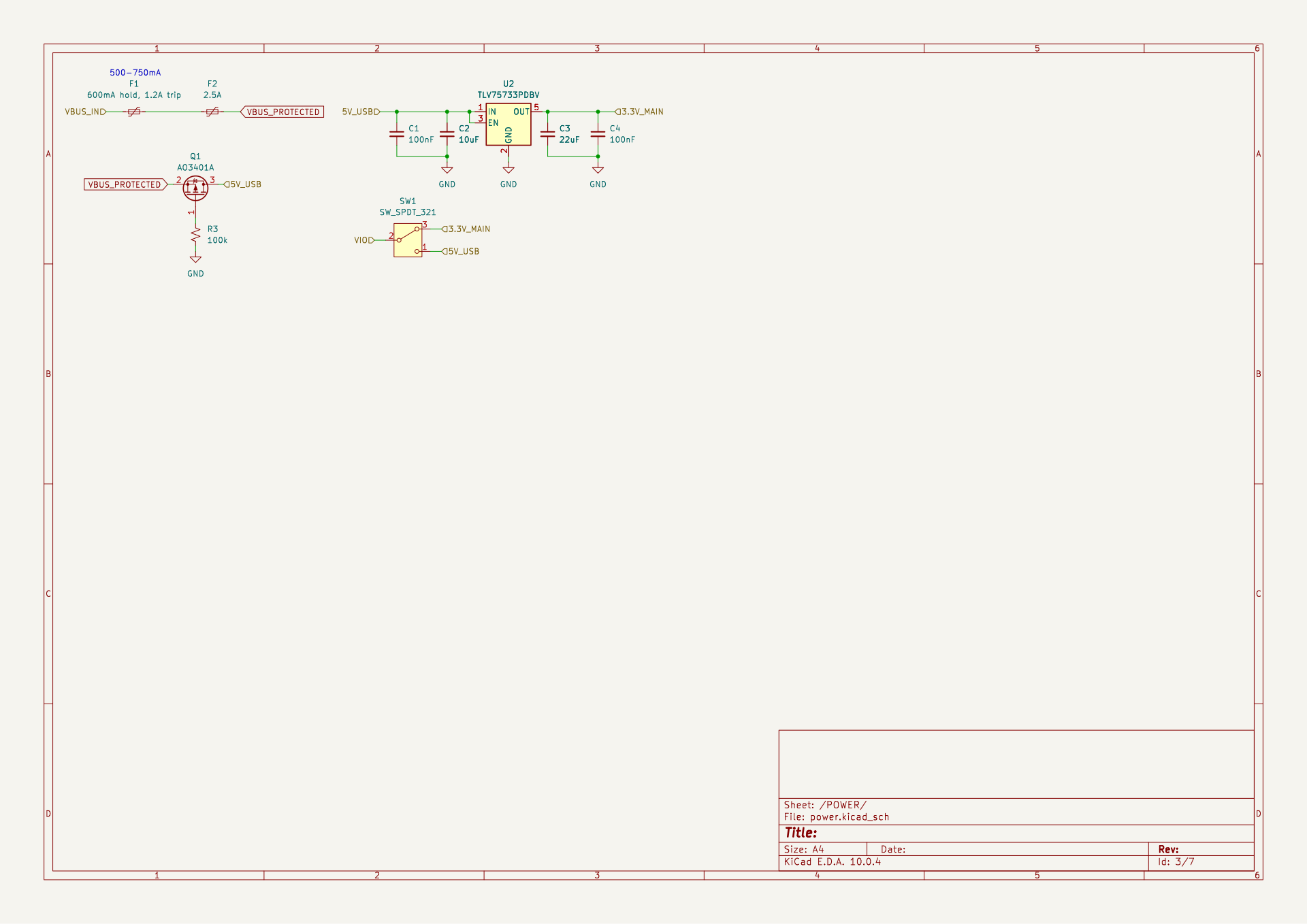
| U2 | 1 | TLV75733PDBV | SOT-23-5 |
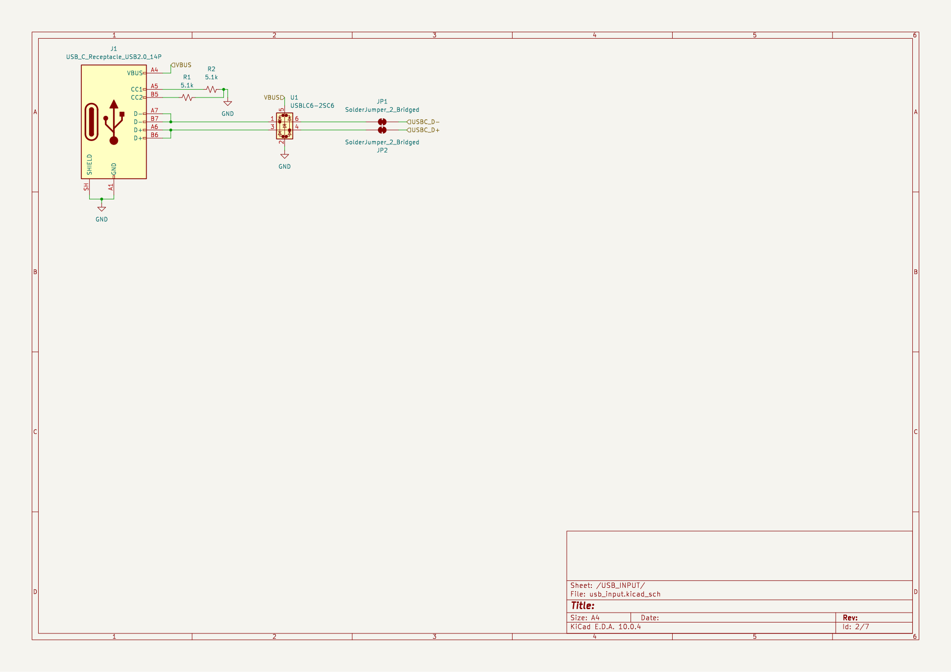
| U1 | 1 | USBLC6-2SC6 | SOT-23-6 |
| C1 C4 C5 C7 C8 C10 | 6 | 100nF | 0805 |
| C6 C9 | 2 | 4.7uF | 0805 |
| C2 | 1 | 10uF | 0805 |
| C3 | 1 | 22uF | 0805 |
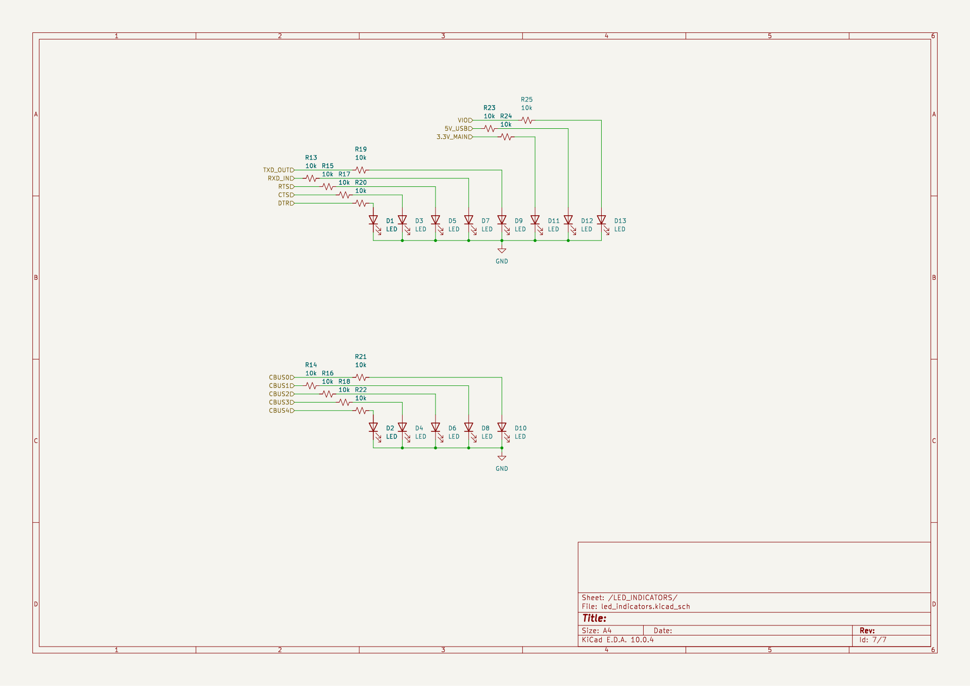
| R4 R10 R12 R13 R14 R15 R16 R17 R18 R19 R20 R21 R22 R23 R24 R25 | 16 | 10k | 0805 |
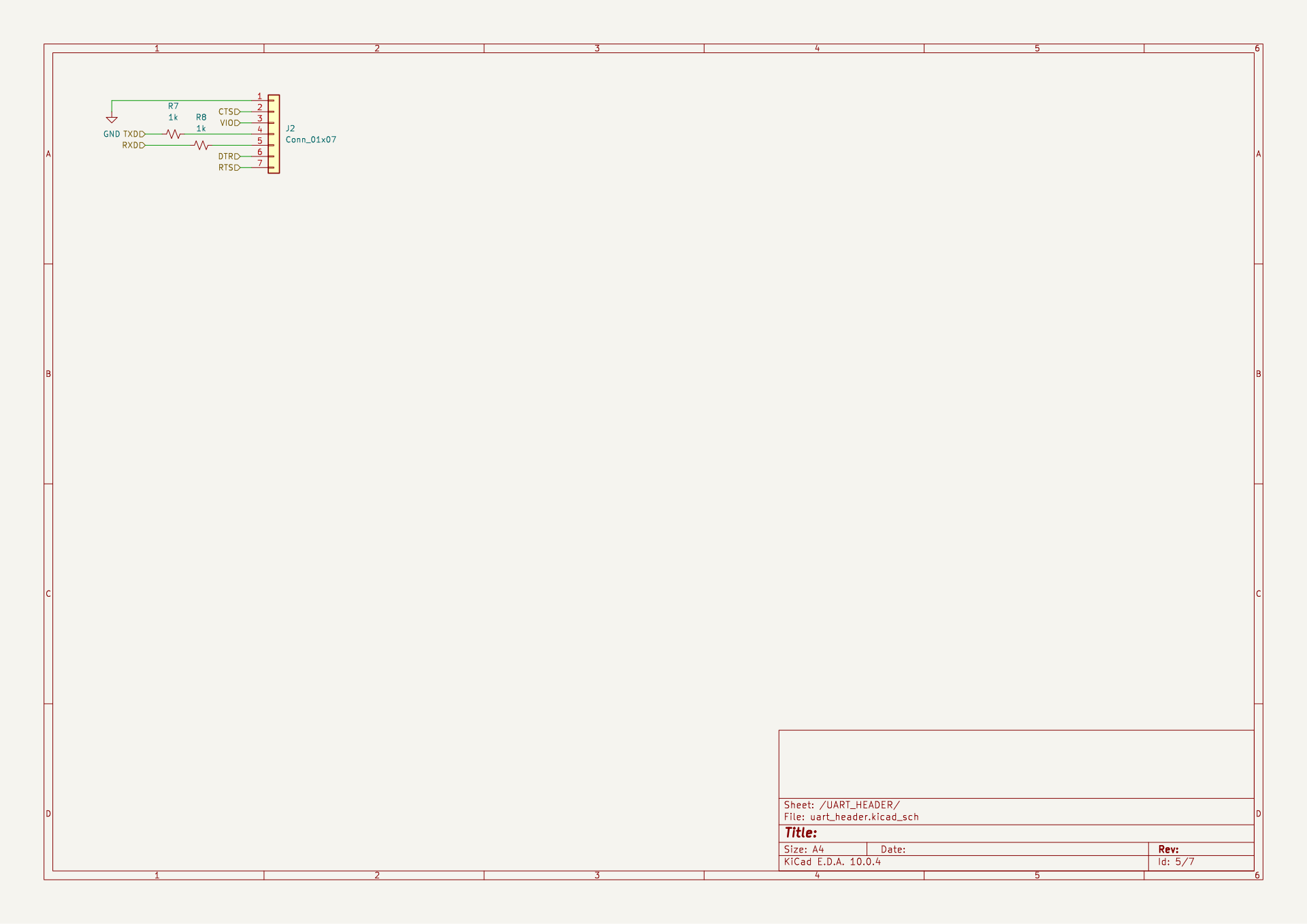
| R7 R8 R9 R11 | 4 | 1k | 0805 |
| R3 | 1 | 100k | 0805 |
| R1 R2 | 2 | 5.1k | 0805 |
| R5 R6 | 2 | 33R | 0805 |
| Q2 Q3 | 2 | BC817 | SOT-23 |
| Q1 | 1 | AO3401A | SOT-23 |
| D1 D2 D3 D4 D5 D6 D7 D8 D9 D10 D11 D12 D13 | 13 | LED | 0805 LED |
| J3 | 1 | Conn_01x04 | 1x4 Header 2.54mm |
| J2 | 1 | Conn_01x07 | 1x7 Header 2.54mm |
| J1 | 1 | USB_C_Receptacle_USB2.0_14P | USB-C Receptacle |
| F1 | 1 | 600mA hold, 1.2A trip | Disc 5.1mm |
| F2 | 1 | 2.5A trip | 0603 |
| SW1 | 1 | SW_SPDT_321 | SPDT Slide switch |
Full BOM available in BOM.csv
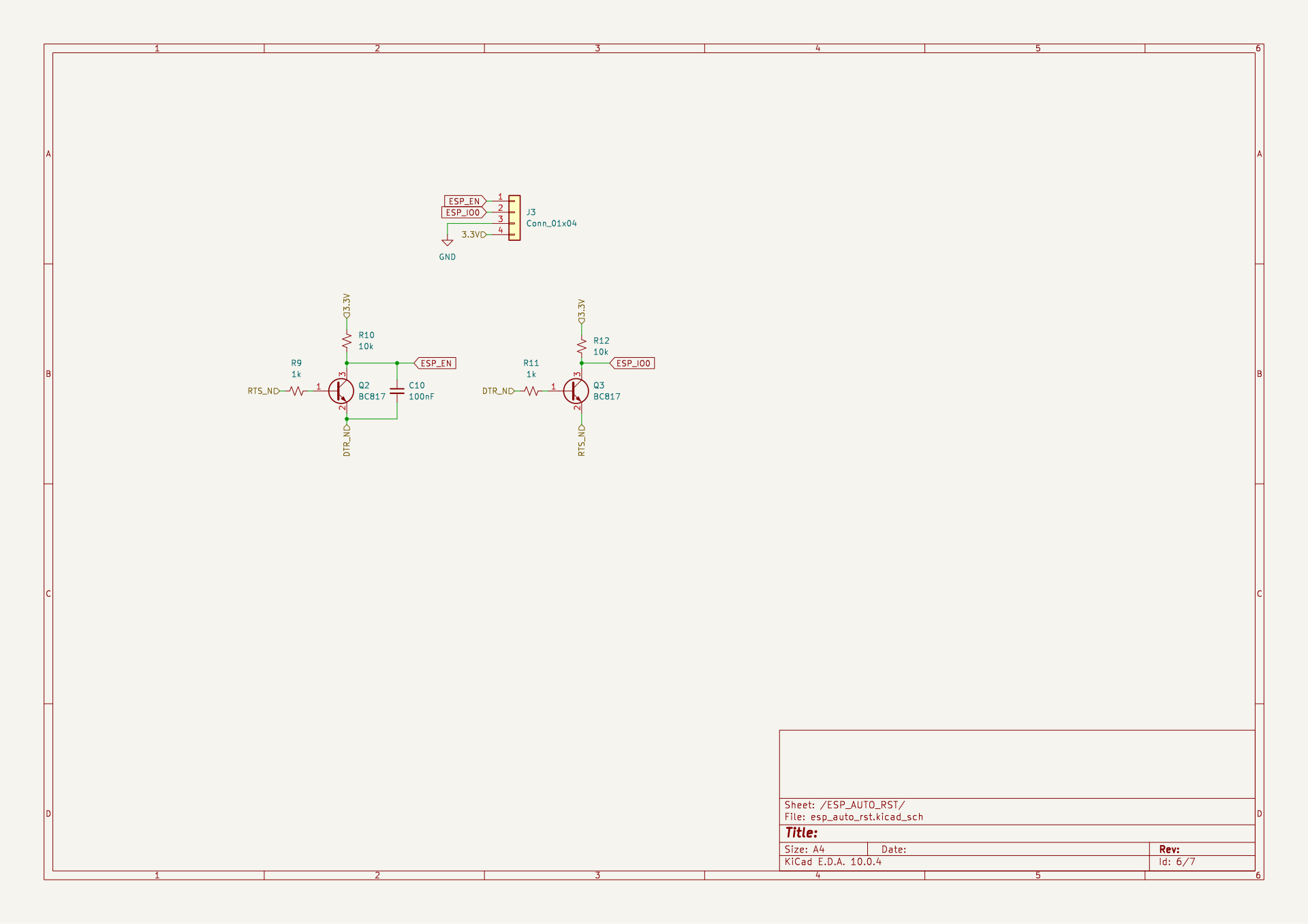
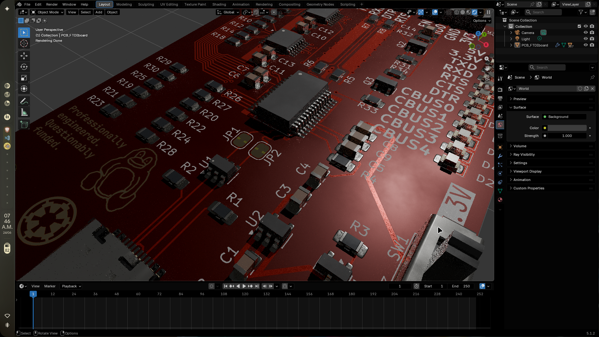
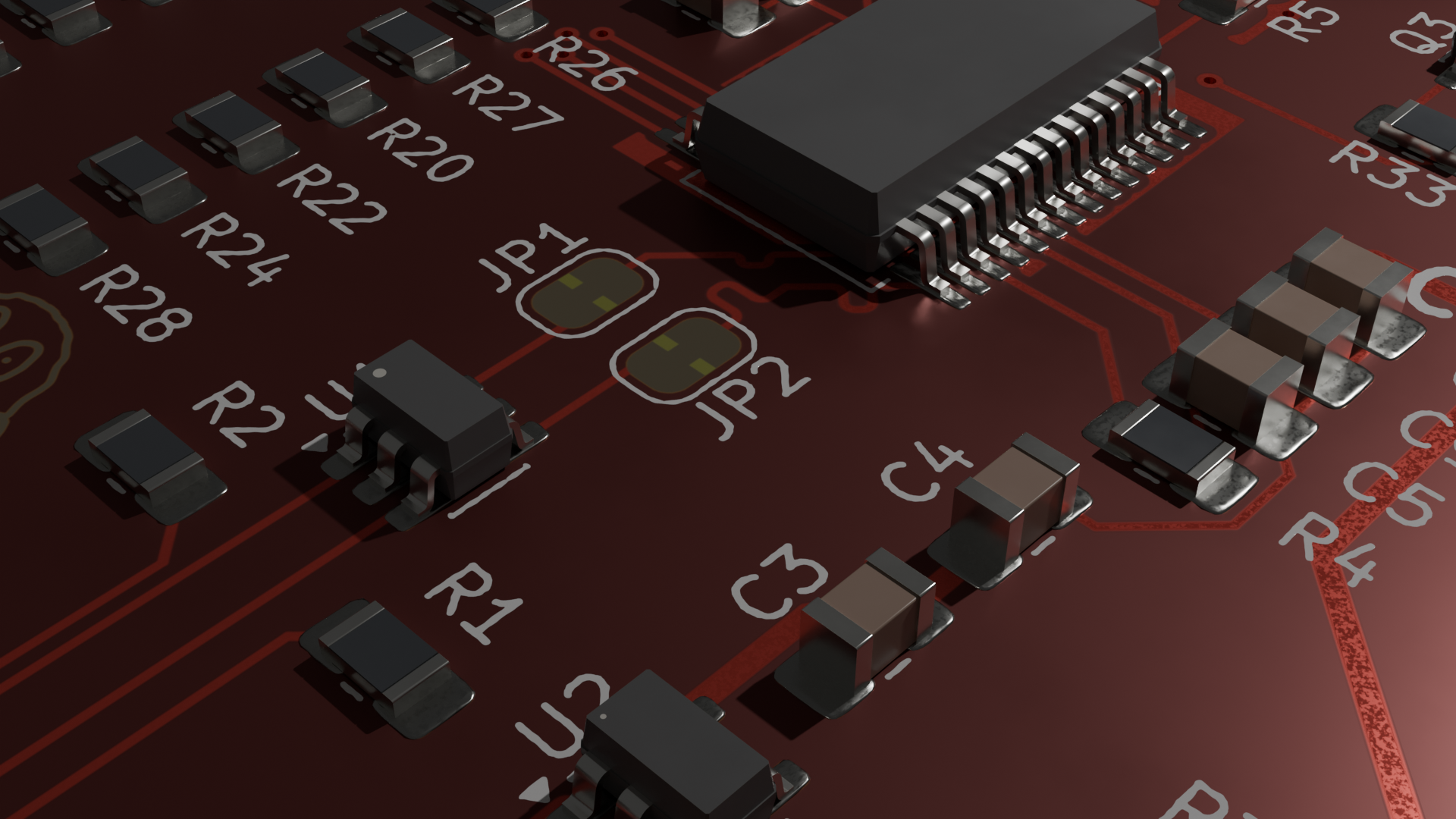
v1.1 board built and tested, self-loopback passes clean. the two v1.0 bugbear fixes (auto-reset latch, VCCIO following the switch) are confirmed gone in this revision.
proof/V1-1/PROOF.mdproof/V1/PROOF.md| Qty | Value | Footprint | References |
|---|---|---|---|
| 16 | 10k | Resistor_SMD:R_0805_2012Metric_Pad1.20x1.40mm_HandSolder | R4, R10, R12, R13, R14, R15, R16, R17, R18, R19, R20, R21, R22, R23, R24, R25 |
| 13 | LED | LED_SMD:LED_0805_2012Metric_Pad1.15x1.40mm_HandSolder | D1, D2, D3, D4, D5, D6, D7, D8, D9, D10, D11, D12, D13 |
| 6 | 100nF | Capacitor_SMD:C_0805_2012Metric_Pad1.18x1.45mm_HandSolder | C1, C4, C5, C7, C8, C10 |
| 4 | 1k | Resistor_SMD:R_0805_2012Metric_Pad1.20x1.40mm_HandSolder | R7, R8, R9, R11 |
| 4 | MountingHole | MountingHole:MountingHole_3.2mm_M3 | H1, H2, H3, H4 |
| 2 | 33R | Resistor_SMD:R_0805_2012Metric_Pad1.20x1.40mm_HandSolder | R5, R6 |
| 2 | 4.7uF | Capacitor_SMD:C_0805_2012Metric_Pad1.18x1.45mm_HandSolder | C6, C9 |
| 2 | 5.1k | Resistor_SMD:R_0805_2012Metric_Pad1.20x1.40mm_HandSolder | R1, R2 |
| 2 | BC817 | Package_TO_SOT_SMD:SOT-23 | Q2, Q3 |
| 2 | SolderJumper_2_Bridged | Jumper:SolderJumper-2_P1.3mm_Bridged_RoundedPad1.0x1.5mm | JP1, JP2 |
| 1 | 100k | Resistor_SMD:R_0805_2012Metric_Pad1.20x1.40mm_HandSolder | R3 |
| 1 | 10uF | Capacitor_SMD:C_0805_2012Metric_Pad1.18x1.45mm_HandSolder | C2 |
| 1 | 2.5A | Fuse_US_Handsoldering_AKL:Fuse_0603_1608Metric | F2 |
| 1 | 22uF | Capacitor_SMD:C_0805_2012Metric_Pad1.18x1.45mm_HandSolder | C3 |
| 1 | 600mA hold, 1.2A trip | Capacitor_THT:C_Disc_D5.1mm_W3.2mm_P5.00mm | F1 |
| 1 | AO3401A | Package_TO_SOT_SMD:SOT-23 | Q1 |
| 1 | Conn_01x04 | Connector_PinHeader_2.54mm:PinHeader_1x04_P2.54mm_Vertical | J3 |
| 1 | Conn_01x07 | Connector_PinHeader_2.54mm:PinHeader_1x07_P2.54mm_Vertical | J2 |
| 1 | FT232RL | Package_SO:SSOP-28_5.3x10.2mm_P0.65mm | U3 |
| 1 | LOGO | customimages:moon | G*** |
| 1 | LOGO | customimages:linuxpenguin-mask | G*** |
| 1 | LOGO | customimages:linuxpenguin_cu | G*** |
| 1 | SW_SPDT_321 | Button_Switch_THT:SW_Slide_SPDT_Straight_CK_OS102011MS2Q | SW1 |
| 1 | TLV75733PDBV | Package_TO_SOT_SMD:SOT-23-5 | U2 |
| 1 | USBLC6-2SC6 | Package_TO_SOT_SMD:SOT-23-6 | U1 |
| 1 | USB_C_Receptacle_USB2.0_14P | Connector_USB:USB_C_Receptacle_HRO_TYPE-C-31-M-12 | J1 |

electromotif208/pcb-portfolio
👨💻 Electronics Engineer 📺 YouTube: ELECTROMOTIF 🔧 Tools: KiCad, EasyEDA 📡 Domains: Power Supply, ESP32, IoT, Embedded Hardware


Plastal-Bot-Builders/RoboCoreDocumentation
RoboCore is a classroom robot kit and coding platform, designed and built in Zambia by Plastal-Bot Builders (Lusaka).

BrandonFors/convention_pcb_badge
Design for a custom pcb badge for opensauce convention and maybe other conventions in the future.

dyu134/ESP-HI-PLUS
The Robot sub-module is a high-performance actuator and sensing expansion board for the ESP-HI-PLUS, designed to transform the device into a mobile or interactive robotic platform.

houseofbigseals/grip_strength_meter_pcb
schematic and pcb for custom esp32 grip strength meter project

Turboblider55/Project_OpenGauge
Modular Vehicle Telemetry and Infotainment Companion via OBD-II
It measures 50 × 75 mm and has 4 copper layers, 1.6 mm thick.
69 parts, built around the FT232RL, TLV75733PDBV, USBLC6-2SC6 and BC817. The full list of its parts is on this page, with links to each part's symbol and footprint where PCBKit's library has them.
From the sneakylizard123-4/FTDIboard repository on GitHub, at the commit this page was made from: the board is kicad/FTDIboard.kicad_pcb and its schematic kicad/FTDIboard.kicad_sch. PCBKit opens the board in the browser, with nothing to install.
Its repository states no licence, so its author keeps all rights: ask sneakylizard123-4 before reusing the design.