
2 layers43.5 × 72 mm

 sm0kbw/pbitx5
My port of Ubitx software to Raspberry Pi Pico
Agc smeter is an open-source printed circuit board by sm0kbw, from the sm0kbw/pbitx repository on GitHub, published under the GPL-3.0 licence. It is a 2-layer board of 40.6 × 29.2 mm with 33 parts on 15 nets, routed with 92 tracks and 16 vias.
It is built around the BAT54A and BAT54S. Its parts include 9 resistors, 7 capacitors, 7 connectors, 4 transistors and 2 diodes.
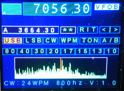
Pbitx is a replacement for the arduino in Ubitx v6, it´s based on the Raspberry Pi Pico micro controller.
It contains software written in C, the code is a rework of the ubitxv6-master branch some files are replaced/added. The name is a combination of Pico and Ubitx resulting in Pbitx.
Changed or replaced files is for instance the file handling CW, it's replaced with my own state machine. I also use my own CI-V interpreter. Beside thiose files I have made a lot of changes in the code, and I like to think that I have simplified some code. I use a set of fonts from http://www.rinkydinkelectronics.com/r_fonts.php/ thank you for those files.
I've added a S-meter and a panorama-mode, both dependent on a extended ND6T AGC ciricuit. The panaroma mode means that a broader frequency span is sweept and presented as s spectrum on the display, this is how it was done in ancient times, of course the reciever isn't usable in this mode. Pbitx has three CW modes, straight key, plain respective iambic bugg mode. CAT is now a subset of the CI-V interrface. For now it's just a couple of commands implemented such as setting and reading the frequency, changing mode and switch between RX and TX mode. The structure of the interpreter makes it very easy to add more of the CI-V commands.
Hardware design files can be found in the PCB folder and the subfolder AGC. There are two Kicad designs the first on is the adapter that replace the Arduino with a RPI Pico controller. The second one is an AGC detector it is used by some functions, S-Meter and a panoram scope, The detector is based on ND6T's design with some extra components added.
This is, of course, a work in progress and features will be added and bugg fixed.
Bengt - SM0KBW 2023-Nov-01
| Qty | Value | Footprint | References |
|---|---|---|---|
| 7 | Conn_01x01_Pin | Connector_Wire:SolderWire-0.5sqmm_1x01_D0.9mm_OD2.1mm | J1, J2, J3, J4, J5, J6, J7 |
| 5 | 100k | Resistor_SMD:R_0603_1608Metric | R1, R5, R6, R7, R9 |
| 4 | 2N7002 | Package_TO_SOT_SMD:SOT-23 | Q1, Q2, Q3, Q4 |
| 3 | 100n | Capacitor_SMD:C_0603_1608Metric | C1, C3, C7 |
| 3 | 10n | Capacitor_SMD:C_0603_1608Metric | C2, C5, C6 |
| 2 | 10k | Resistor_SMD:R_0603_1608Metric | R3, R10 |
| 2 | 1k | Resistor_SMD:R_0603_1608Metric | R2, R4 |
| 1 | 1u | Capacitor_SMD:C_0805_2012Metric | C4 |
| 1 | BAT54A | Package_TO_SOT_SMD:SOT-23 | D2 |
| 1 | BAT54S | Package_TO_SOT_SMD:SOT-23 | D1 |
The 29 most common of 33 parts.

mnemocron/FHNW-Pro4E-FS19T8-3DPrinterBoard-STM32
Marlin 2.0 compatible 3D printer board based on STM32F103 (KiCad)

95lux/aware01
Aarebot is a dynamic realtime sampler built as a Eurorack module. At its core is a stereo tape-style engine with a hot-swapping record/playback buffer - this enables to record and play simultaneously.

hatlabs/HALMET-hardware
Hat Labs Marine Engine & Tank interface hardware design files

tomek-szczesny/m1s-fpga-playground
An add-on board with FPGA for ODROID M1S.

jodhsinghnahal/piezo_matlab
Simulation, circuit and PCB design repository for investigating piezoelectric energy harvesting (PEH) interfaces under conventional vibration excitation and underwater acoustic excitation.

OAK-WJR/rocket-flight-computer
Amateur rocket flight computer: single-board KiCad PCB (STM32H743), firmware and diagnostics

MycroftAI/hardware-mycroft-mark-II
Mycroft's Mark II Rpi mechanical, electrical and industrial designs

It measures 40.6 × 29.2 mm and has 2 copper layers, 1.6 mm thick.
33 parts, built around the BAT54A and BAT54S. The full list of its parts is on this page, with links to each part's symbol and footprint where PCBKit's library has them.
From the sm0kbw/pbitx repository on GitHub, at the commit this page was made from: the board is PCB/AGC/agc_smeter.kicad_pcb and its schematic PCB/AGC/agc_smeter.kicad_sch. PCBKit opens the board in the browser, with nothing to install.
Its repository publishes it under the GPL-3.0 licence: you may reuse it on that licence's terms (keep the author's notice, and for a copyleft licence share your changes alike).