4 layers46 × 186 mm
M3 assy r1
OAK-WJR/rocket-flight-computer
Amateur rocket flight computer: single-board KiCad PCB (STM32H743), firmware and diagnostics
135 parts

 OAK-WJR/rocket-flight-computer
Amateur rocket flight computer: single-board KiCad PCB (STM32H743), firmware and diagnostics
Assembly review is an open-source printed circuit board by OAK-WJR, from the OAK-WJR/rocket-flight-computer repository on GitHub. It is a 4-layer board of 46 × 238 mm with 208 parts on 162 nets, routed with 2,037 tracks and 608 vias.
It is built around the SAM-M10Q-00B, MS561101BA03-50 and ICM-45686, with the AO3400A, AON6403 and AON7524 among its other parts. Its parts include 79 resistors, 63 capacitors, 6 transistors, 6 connectors and 5 ICs.


Status: design only. No board has been built, powered or flown. Every result below comes from CAD checks, circuit simulation or software tests on a computer, never from hardware.
This is a flight computer for a student high-power rocket. It is one 46 × 238 mm, four-layer circuit board that slides into a 54.66 mm inside-diameter airframe. It runs from a 2-cell LiPo battery, uses an STM32H743 microcontroller, reads an IMU (ICM-45686), a barometer (MS5611) and GPS (SAM-M10Q), logs to flash memory, talks over USB, powers a camera, drives four fin servos for roll control, and has two separately fused circuits to fire the parachute charge. The current design is revision M3-ASSY-R2 (28 Sep 2026).

KiCad 3D render of the top side of M3-ASSY-R2 (46 × 238 mm).
There is no video, because the board has not been built. What can be shown and re-run today:
tools/check.sh runs KiCad's design-rule check, electrical-rule check and schematic-vs-PCB check. Output on 2026-11-01 (KiCad 10.0.6):
DRC violations 0  unconnected 0  schematic parity 0  ERC 0
metadata / 3D model audit: OKm3_design/sim_r2/ found a flaw in the design: with a fresh 8.4 V battery, firing into a shorted igniter pulled the battery below 5 V for 3.9 ms (long enough that the computer could reset and miss the second parachute charge) and pushed 131 A through a transistor rated for 112 A. Adding a 2 Ω pulse resistor to each channel fixed it in simulation (4.1 A, battery stays above 8.2 V).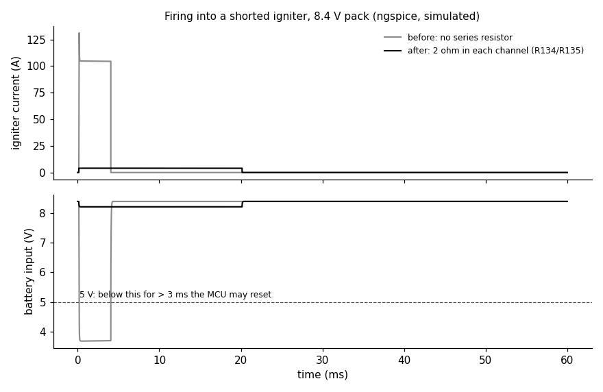
Simulated, not measured. Grey: before the fix. Black: with the 2 Ω resistors. The 20 ms pulse length is a rule the future firmware must follow.
The portfolio page for this project is 8a ("Rocket Flight Computer Design").
flowchart LR
  BAT[2S LiPo battery] --> PWR[power switch, reverse and over-voltage protection, 3.3 V supply]
  PWR --> MCU[STM32H743 microcontroller]
  SEN[IMU, barometer, GPS] --> MCU
  MCU --> LOG[flash log]
  MCU --> USB[USB diagnostics]
  MCU --> CAM[camera power and UART]
  BAT --> ACT[actuator power switch]
  ACT --> SRV[four fin servos]
  ACT --> ARM[arming plug: a full break] --> PYRO[two fused parachute channels]
  MCU --> SRV
MCU --> PYROreference/m1_power_actuator/.m3_design/check_actuators.py) reads the PCB copper and fails if anything bypasses it.diagnostics/ turn a report into a list of likely faults.docs/R2_VERIFICATION.md).No hardware is needed for any of these. Tested on macOS with KiCad 10.0.6, ngspice 46 and Python 3.9 on 2026-11-01.
git clone https://github.com/OAK-WJR/rocket-flight-computer.git
cd rocket-flight-computer

tools/check.sh                          # DRC + ERC + schematic parity + 3D/metadata audit (needs KiCad 10.0.x)
python3 m3_design/check_actuators.py    # arming / pyro / servo safety contract -> "actuator safety contract: OK"
python3 m3_design/sim_r2/run.py         # ngspice suite -> {'PASS': 135, 'OLD-FAIL': 6, 'INFO': 8, 'DEMO': 2}
python3 m3_design/sim_r2/plot_short.py  # redraws docs/images/shorted_igniter_sim.png (needs matplotlib)
python3 tools/export_fab.py             # Gerber zip + JLCPCB BOM/CPL into m3_design/assembly_review/fab/

python3 -m venv .venv && .venv/bin/pip install -r diagnostics/requirements-lock.txt
.venv/bin/python -m unittest discover -s diagnostics -t . -p 'test_*.py'      # 173 tests, OK (1 skipped)
(cd m3_firmware && PYTHONPATH=.. python3 -m unittest test_firmware test_gnss test_usb)  # 41 tests, OK

open m3_design/assembly_review/m3.kicad_pro # open the design in KiCad 10KICAD_CLI=/path/to/kicad-cli before tools/check.sh.OLD-FAIL rows in the simulation are the pre-fix design, kept on purpose for comparison.m3_firmware/build.py needs the Arm GNU Toolchain 15.2.rel1 in m3_firmware/toolchain/ and the maker datasheet PDFs it hash-checks (not committed, for copyright). It also refuses to build for R2 on purpose, because no R2 firmware exists yet. Prebuilt bench images for the older R1 board are in m3_firmware/build_assembly_*/. Do not run them on an R2 board.tools/export_fab.py (see docs/ORDERING.md), then need a 2S LiPo, an ST-Link/SWD probe and a USB-C cable. None of this has been done.| Path | What is in it |
|---|---|
m3_design/assembly_review/ | The KiCad 10 project (the single source of truth): 14 schematic sheets, PCB, local footprints, symbols and 3D models, schematic PNG/SVG exports in sheets/, review notes |
m3_design/sim_r2/ | ngspice suite for the actuator and parachute circuits (run.py, RESULTS.md, FINDINGS.md, plot_short.py) |
m3_design/check_actuators.py | Safety check that reads the PCB netlist |
m3_firmware/ | Bench diagnostic firmware v0.8.1 (C, STM32 HAL + TinyUSB) for the R1 board, pin bindings, host-side tests |
diagnostics/ | Python host tools: USB/SWD readout, log recovery, fault localisation, test-point map |
docs/ | Ordering guide, part-by-part verification, actuator merge record, design rationale, FMEA, simulation notes, design history |
quality_audit/ | Board audit: conflicting part numbers, 3D model paths, DRC/ERC evidence |
reference/ | Older boards kept for comparison: M1 power/actuator board, M3-ASSY-R1 |
tools/ | check.sh (board gate), export_fab.py (fabrication files), JLCPCB stock and orientation helpers |
STATUS.md | Every requirement and what is and is not verified |
AGENTS.md, CLAUDE.md | The rules given to the AI coding assistants (see Credits) |
What is done (on a computer only):
What is not done:
STATUS.md, docs/R2_VERIFICATION.md §4).Other branches: m3-assy-r11 is the development line. It holds the later redesigns R3 to R10 (Oct 2026) and the compact R11 candidate (Nov 2026), committed by a collaborator, and the R10 bench diagnostics; each earlier revision is in its history. They are not part of the R2 design described here.
Jerry Wu (Jiarui Wu): the project and its requirements: one board that fits the 54.66 mm airframe, built-in USB diagnostics, at most three PCB iterations. I chose to merge the two earlier boards into one, set the system constraints, made the design decisions recorded as "owner rulings" (for example two independently fused parachute channels, and keeping the backup altimeter fully separate), and reviewed the layout, flagging routing problems such as unwanted zigzag traces.
AI coding assistants: they produced most of the schematics, PCB layout, simulations, firmware and scripts from my requirements and decisions.
Co-Authored-By: Claude line. AGENTS.md (read by Codex, and by Claude Code through CLAUDE.md) holds the safety and routing rules they had to follow.Collaborator and existing work:
m3_firmware/vendor/; KiCad library 3D models (CC-BY-SA 4.0 with exception); footprints and 3D models converted from the EasyEDA/LCSC library with easyeda2kicad. Details and licences: THIRD_PARTY_NOTICES.md.| Qty | Value | Footprint | References |
|---|---|---|---|
| 24 | 10k | rocket:R0402 | R10, R11, R104, R121, R124, R128, R129, R131, R132, R140, R141, R143, R144, R154, R155, R156 +8 |
| 15 | 100nF | rocket:C0402 | C5, C13, C14, C15, C16, C17, C18, C21, C24, C29, C30, C31, C32, C33, C160 |
| 10 | 10k 0.1% | rocket:R_0603_1608Metric | R75, R76, R78, R88, R89, R90, R91, R92, R102, R110 |
| 9 | 22uF | rocket:C0805 | C6, C7, C8, C9, C10, C11, C34, C150, C151 |
| 8 | 1k | rocket:R0402 | R105, R127, R130, R133, R139, R142, R145, R160 |
| 7 | 100nF 50V X7R 10% | rocket:C_0603_1608Metric | C71, C74, C83, C90, C93, C128, C140 |
| 7 | 10nF | rocket:C0603 | C60, C94, C122, C127, C129, C139, C141 |
| 6 | 22uF 25V X7R 10% | rocket:M3_GRM32_1210 | C72, C73, C75, C76, C82, C92 |
| 5 | 1k 1% | rocket:R_0603_1608Metric | R74, R77, R100, R101, R103 |
| 5 | 220R | rocket:R0805 | R32, R33, R126, R138, R162 |
| 4 | 100k | rocket:R0402 | R60, R120, R122, R123 |
| 4 | 1k 0805 | rocket:R0805 | R150, R151, R152, R153 |
| 3 | 2.2uF | rocket:C0603 | C19, C20, C120 |
| 3 | 4.7k | rocket:R0402 | R12, R13, R125 |
| 3 | GND | rocket:M3_TestPad_1.5 | TP74, TP88, TP124 |
| 2 | 10pF | rocket:C0402 | C25, C26 |
| 2 | 1uF 50V X7R 10% | rocket:C_1206_3216Metric | C80, C91 |
| 2 | 220nF 25V X7R | rocket:C0603 | C126, C138 |
| 2 | 2R 1% 2W pulse | rocket:R2512 | R134, R135 |
| 2 | 4.7nF 50V C0G 5% | rocket:C_0603_1608Metric | C70, C81 |
| 2 | 4.7uF | rocket:C0603 | C23, C28 |
| 2 | 4.7uH | rocket:IND-SMD_L4.0-W4.0 | L1, L2 |
| 2 | 5.1k | rocket:R0402 | R7, R8 |
| 2 | AO3400A | rocket:SOT-23-3_L2.9-W1.3-P1.90-LS2.4-BR | Q122, Q123 |
| 2 | AON6403 | rocket:PDFN-8_L5.6-W5.2-P1.27-LS6.1-BL | Q120, Q121 |
| 2 | AON7524 | rocket:M3_AON7524_DFN3x3A | Q124, Q125 |
| 2 | RAW_PROTECTED | rocket:M3_TestPad_1.5 | TP70, TP81 |
| 1 | 1.65k 0.1% | rocket:R_0603_1608Metric | R84 |
| 1 | 1.78k 0.1% | rocket:R_0603_1608Metric | R70 |
| 1 | 172k 0.1% | rocket:R_0603_1608Metric | R71 |
| 1 | 1M 0.1% | rocket:R_0603_1608Metric | R80 |
| 1 | 1N5819WS | rocket:SOD-323_L1.8-W1.3-LS2.5-RD | D123 |
| 1 | 1uF | rocket:C0603 | C22 |
| 1 | 1uF 25V X7R 10% | rocket:C_0603_1608Metric | C86 |
| 1 | 25MHz CL8pF | rocket:CRYSTAL-SMD_4P-L3.2-W2.5-BL | Y1 |
| 1 | 280k 0.1% | rocket:R_0603_1608Metric | R81 |
| 1 | 2M 0.1% | rocket:R_0603_1608Metric | R82 |
| 1 | 30.9k 0.1% | rocket:R_0603_1608Metric | R72 |
| 1 | 300k 0.1% | rocket:R_0603_1608Metric | R83 |
| 1 | 330uF 35V | rocket:M3_OSCON_F12 | C84 |
| 1 | 44.2k 0.1% | rocket:R_0603_1608Metric | R87 |
| 1 | 470nF 25V X7R 10% | rocket:C_0603_1608Metric | C85 |
| 1 | 470uF 25V | rocket:CAP-SMD_BD8.0-L8.3-W8.3-LS9.0-FD_H10.5 | C121 |
| 1 | 47pF 50V C0G 5% | rocket:C_0603_1608Metric | C77 |
| 1 | 6.2k 1% | rocket:R0402 | R9 |
| 1 | 6.8uH | rocket:M3_SRP5030TA | L3 |
| 1 | 66.5k 1% | rocket:R_0603_1608Metric | R85 |
| 1 | 80.6k 0.1% | rocket:R_0603_1608Metric | R86 |
| 1 | ACT_GATE | rocket:M3_TestPad_1.5 | TP121 |
| 1 | AP63203WU-7 | rocket:TSOT-26_L2.9-W1.6-P0.95-LS2.8-BL | U2 |
| 1 | AP63300WU-7 | rocket:M3_AP63200_TSOT26 | U8 |
| 1 | ARM: RAW / BUS2 / BUS1 / RAW | rocket:M3_DB128V_4P | J120 |
| 1 | B340A-13-F | rocket:D_SMA | D9 |
| 1 | BAT+ / GND / SW / SW | rocket:M3_DB128V_4P_Entry | J1 |
| 1 | BAT54A | rocket:SOT-23-3_L2.9-W1.3-P1.90-LS2.4-BR | D120 |
| 1 | BAT54S | rocket:SOT-23-3_L2.9-W1.3-P1.90-LS2.4-BR | D122 |
| 1 | BAT_ENABLE | rocket:M3_TestPad_1.5 | TP84 |
| 1 | BAT_FAULT_N | rocket:M3_TestPad_1.5 | TP85 |
| 1 | BAT_ILIM | rocket:M3_TestPad_1.5 | TP89 |
| 1 | BAT_IN | rocket:M3_TestPad_1.5 | TP80 |
| 1 | CAM 5V / GND / RX / TX | rocket:M3_DB128V_4P | J9 |
| 1 | CAM_5V | rocket:M3_TestPad_1.5 | TP72 |
| 1 | CAM_ILIM | rocket:M3_TestPad_1.5 | TP73 |
| 1 | CAM_INPUT_LIMITED | rocket:M3_TestPad_1.5 | TP71 |
| 1 | CAM_IO_3V3 | rocket:M3_TestPad_1.5 | TP90 |
| 1 | CAM_RX_TEST | rocket:M3_TestPad_1.5 | TP75 |
| 1 | CAM_TX_TEST | rocket:M3_TestPad_1.5 | TP76 |
| 1 | CAM_UART_OE | rocket:M3_TestPad_1.5 | TP91 |
| 1 | E1- / E1+ / E2+ / E2- | rocket:M3_DB128V_4P | J121 |
| 1 | ICM-45686 | rocket:LGA-14_L3.0-W2.5-P0.50-TL | U4 |
| 1 | LOGIC_SOURCE_ST | rocket:M3_TestPad_1.5 | TP87 |
| 1 | MLT-8530 | rocket:BUZ-SMD_4P-L8.5-W8.5-P8.50-BR | LS120 |
| 1 | MS561101BA03 | rocket:SENSORS-SMD_MS5611-01BA03 | U5 |
| 1 | PULL-PIN 1x2 | rocket:M3_PULLPIN_1x2 | J123 |
| 1 | PYRO1_GATE | rocket:M3_TestPad_1.5 | TP122 |
| 1 | PYRO2_GATE | rocket:M3_TestPad_1.5 | TP123 |
| 1 | RAW_ACT | rocket:M3_TestPad_1.5 | TP120 |
| 1 | RED | rocket:M3_NCD0805R1_K1 | LED1 |
| 1 | SAM-M10Q-00B | rocket:LCC-20_L15.5-W15.5-P1.90_SAM-M10Q-00B | U6 |
| 1 | SERVO 3x4 | rocket:HDR-TH_12P-P2.54-V-M-R3-C4-S2.54 | J122 |
The 190 most common of 208 parts.
OAK-WJR/rocket-flight-computer
Amateur rocket flight computer: single-board KiCad PCB (STM32H743), firmware and diagnostics

OAK-WJR/rocket-flight-computer
Amateur rocket flight computer: single-board KiCad PCB (STM32H743), firmware and diagnostics

misko/prompt2device
The separate vNext PCB skill and orchestrator package is available alongside the reference workflow below; existing projects keep their accepted toolchain until an explicit migration.


cUDGk/vrc-fbt-hardware
VRChat向けフルボディトラッキング基板 — ハブ+デイジーチェーン端末・数と位置を自由に変更可能・KiCad/OpenSCAD一式

Majorwhiskey/gps-lora
Theoros is a USB-C GPS logger and LoRa tracker built on the ESP32-S3. It logs 1 Hz u-blox M10 fixes to microSD, shows status on an OLED and sends AES-128-CCM encrypted position over 868 MHz LoRa.

NCSU-High-Powered-Rocketry-Club/FIRM-KiCad
Full and open hardware design for FIRM


It measures 46 × 238 mm and has 4 copper layers, 1.6 mm thick.
208 parts, built around the SAM-M10Q-00B, MS561101BA03-50, ICM-45686 and AO3400A. The full list of its parts is on this page, with links to each part's symbol and footprint where PCBKit's library has them.
From the OAK-WJR/rocket-flight-computer repository on GitHub, at the commit this page was made from: the board is m3_design/assembly_review/m3.kicad_pcb and its schematic m3_design/assembly_review/actuator_power.kicad_sch. PCBKit opens the board in the browser, with nothing to install.
Its repository states no licence, so its author keeps all rights: ask OAK-WJR before reusing the design.