Skip to the content
2 layers53.3 × 40.6 mmUsb audio, the printed circuit board in 3D

Compact USB Audio Adapter

Size
53.3 × 40.6 mm
Copper layers
2
Thickness
1.6 mm
Parts
78
Nets
56
Pads
236
Tracks, vias
698, 90
Pours
2
Routed
Yes
KiCad
KiCad 3
Created
10 Dec 2019
Updated
10 Dec 2019

Overview

Usb audio is an open-source printed circuit board by skiselev, from the skiselev/usb_audio repository on GitHub, published under the GPL-3.0 licence. It is a 2-layer board of 53.3 × 40.6 mm with 78 parts on 56 nets, routed with 698 tracks and 90 vias.

It is built around the PLR135/T8, AD8656AR and OPA2353EA, with the PCM2902CDB and REG103UA-5 among its other parts. Its parts include 32 capacitors, 27 resistors, 6 ICs, 4 connectors and 3 switches. It belongs with the audio and music boards of this library.

Main components

5

README

README.md

Compact USB Audio Adapter

Introduction

I was looking for a USB audio adapter for my Intel Galileo projects, and surprisingly I was not able to find a compact USB audio adapter which will offer line input or digital (optical) input and output. Most USB audio dongles available on the market are intended to be used with a headset and only offer monophonic microphone input. One exception was Behringer UCA202 which is bulky for my projects. And so I've designed this adapter.

Overview

This USB Audio adapter can be used with small SBCs like Intel Galileo, Raspberry Pi, or BeagleBone Black to provide high quality audio input and output. Its size is only 2.1 x 1.6 inches (53.44 x 40.74 mm). This USB Audio adapter will also work with regular PCs, Android based smartphones and tablets, or almost everything else that supports USB audio. It is based on popular Texas Instruments (was Burr Brown) PCM2902C, and schematic mostly follows Texas Instrument's reference design.

Photos

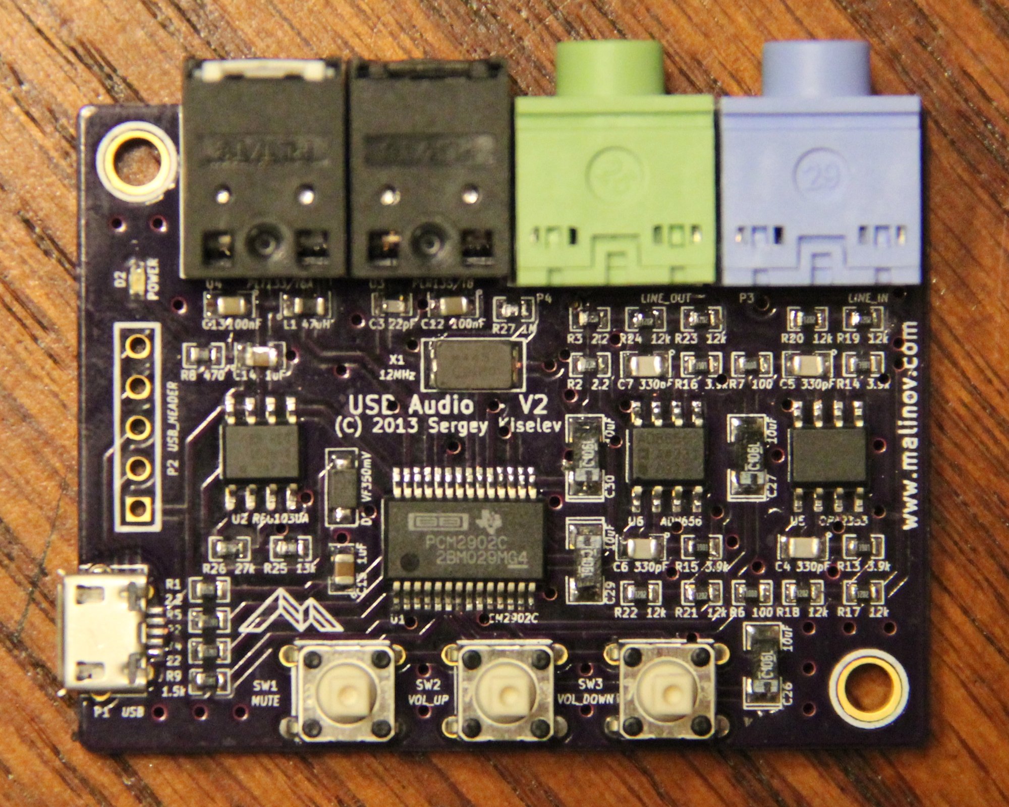
Top side

USB Audio - Front

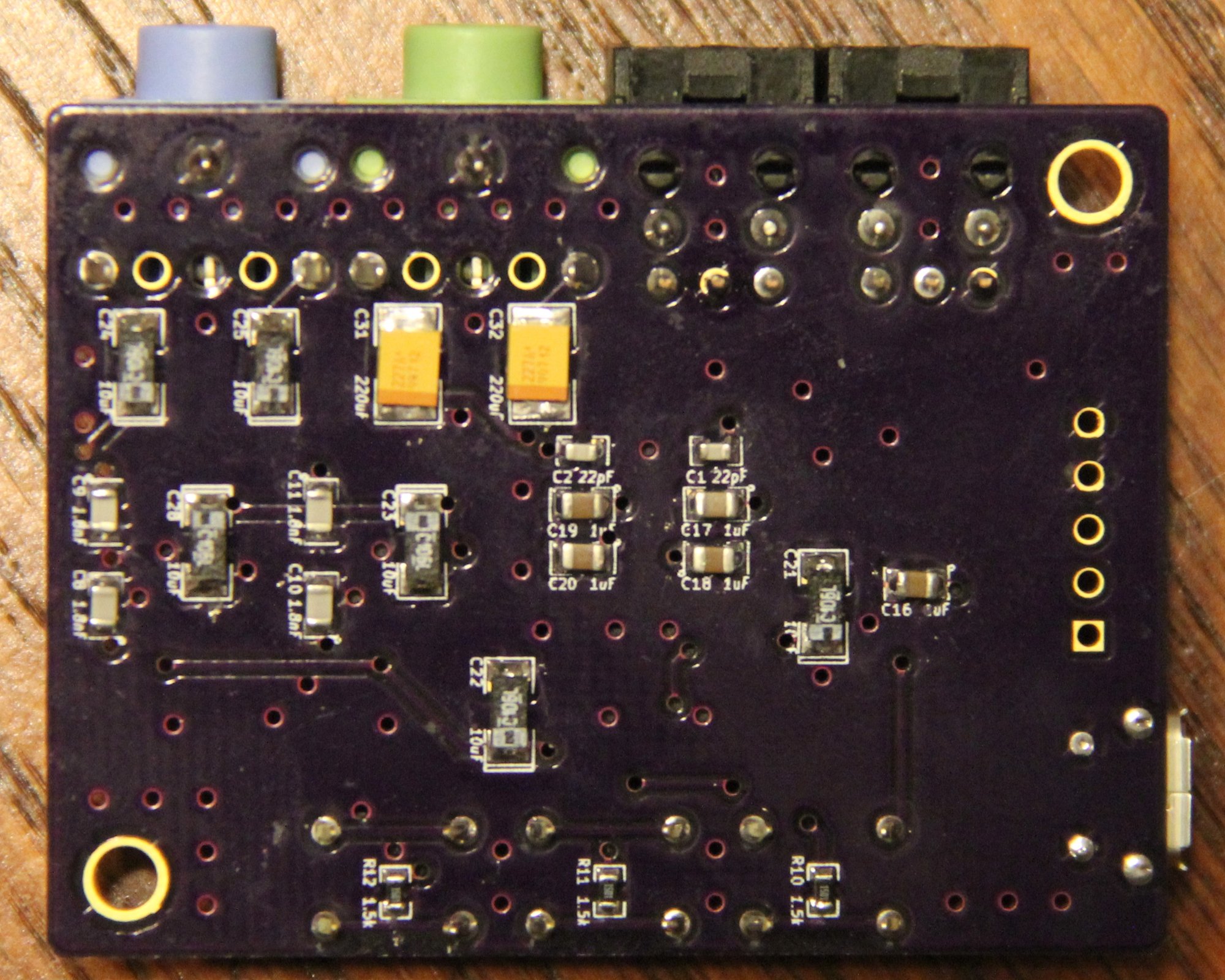
Bottom side

USB Audio - Back

Design

As mentioned above the main component is Texas Instruments PCM2902 USB audio codec IC (U1). Additionally the circuit uses Texas Instruments REG103UA LDO IC for conditioning power for the analog circuitry (U2) and a pair of dual channel operational amplifier ICs that work as low pass filters for input and output (U5 and U6).

Schematic and PCB Layout

Schematic - Version 2.0

PCB Layout - Version 2.0

Design Modifications and Components' Substitution

There is a lot of flexibility in the design:

  • The USB audio codec IC (U1) can be PCM2902, PCM2906, PCM2900, and PCM2904.
    • PCM2902 and PCM2906 provide S/PDIF digital interface. PCM2900 and PCM2904 do not provide it.
    • The difference between PCM2902 and PCM2906 or between PCM2900 and PCM2904 is very subtle: PCM2900 and PCM2902 specify 100mA as Maxpower value in USB descriptor, while PCM2904 and PCM2906 specify 500mA. Operating systems should be using Maxpower values to estimate power consumption by the attached USB devices and disconnect USB devices if host is unable to supply enough power.
    • If using codec without S/PDIF support the components related to optical input and output should not be mounted.
    • I used the latest PCM290xC revision. Other, older revisions don't differ significantly and can be used as well.
  • The REG103 LDO (U2) is optional and can be removed to lower the cost at some audio quality degradation. It is also possible to replace it with cheaper LDO with minor schematic and PCB modifications.
  • The design uses high-speed operational amplifiers. Either one of these op amps or both can be bypassed, leaving just 100 ohm / 10 uF capacitors for audio coupling. It is also possible to use other compatible operational amplifiers (important characteristics: single power supply 3.3V, rail-to-rail)
  • Both input and output parts are optional. For example if only ADC part is needed, no need to assemble components related to audio output. Same applies for DAC only (audio output only) use. In this case I suggest grounding audio inputs of PCM2902 to avoid noise.
  • The PCB supports two options for connecting to USB:
    • Using Micro USB connector
    • Using 5-pin header (it is also possible to solder a USB cable directly to the board instead of this header).
  • Volume control buttons are optional

Assembly Notes

Due to project's size and component availability the project mostly uses SMT components. I used through hole components for components that are subject to physical stress (connectors and buttons). It it is not too difficult to solder SMT components it with some practice. Here are some tips:

  • Have a well lighten workspace.
  • Use a low power (25W or so) soldering iron with thin tip, better yet a temperature controlled soldering station. Keep the tip of soldering iron clean.
  • Use thin solder with flux. Have some desoldering braid to remove accidental solder bridges or excess solder.
  • I found it convenient first to put some solder on a first pad of a component (or on two opposite pads in case of an IC. When put the component using tweezers and heat the pad at the same time. Next double check component orientation and solder remaining pads. Note that diodes and tantalum capacitors are polarized, so the orientation is important.
  • Solder ICs first, next solder micro USB connector.
  • After that solder all the resistors, inductor, and smaller (0603 and 0805) capacitors on the top side, going from ICs to sides of the board.
  • Solder Schottky diode, LED, crystal resonator, and tantalum capacitors. Make sure to check that they are oriented properly.
  • Turn the board up side down, and solder resistors and the capacitors on the bottom side.
  • Finally solder through hole components: connectors, optical modules, buttons.
  • Clean the flux remains with some alcohol. (Be careful not to get alcohol/flux inside optical modules, or maybe solder them after cleaning the board).
  • Search the Internet for SMT soldering tutorials.

Bill of Materials

USB Audio project on Mouser.com - View and order all components except of the PCB, screws and nuts.

USB Audio project on OSH Park - View and order PCB.

Component typeReferenceDescriptionQuantityPossible sources and notes
PCBUSB Audio PCB - V21Order at OSH Park or from any other PCB manufacturer using Gerber files from gerber folder.
CapacitorC1 - C322pF C0G SMT 0603 capacitor3Mouser 77-VJ0603A220JXACBC. Note: C3 is not needed if not implementing optical S/PDIF input.
CapacitorC4 - C7330pF C0G SMT 0805 capacitor4Mouser 77-VJ0805A331KXACBC
CapacitorC8 - C111.8nF C0G SMT 0805 capacitor4Mouser 81-GRM215C1H182JA01D
CapacitorC12, C13100nF X7R SMT 0805 capacitor2Mouser [80-C0805C104K3R7210](https://www.mouser.com/ProductDetail/80-C0805C104K3R7210]. Note: These capacitor are not needed if not implementing optical S/PDIF input and output.
CapacitorC14 - C201uF X7R SMT 0805 capacitor7Mouser [80-C0805C105K4R](https://www.mouser.com/ProductDetail/80-C0805C105K4R]
CapacitorC21 - C3010uF tantalum SMT capacitor10Mouser 74-593D106X9016A2TE3
CapacitorC31, C32220uF tantalum SMT capacitor2Mouser 581-TLNT227M010R1300. Note: Use the recommended value if driving low impedance loads (for example headphones). For high impedance loads (e.g. line output connected to an amplifier) cheaper 10uF capacitors can be used. See previous line for part number.
Schottky DiodeD1Schottky diode with low voltage drop (350mV)1Mouser 771-PMEG2010ER115
LEDD20603 LED1Mouser 78-VLMTG1300-GS08. Any color can be used :-) The suggested part is "pure" green. It is too bright to my taste, so if using it consider increasing value of R8. Or use "conventional" green and save a few cents.
InductorL147uH SMT 0805 inductor1Mouser 963-LBR2012T470K. Note: This inductor is not needed if not implementing optical S/PDIF input.
ConnectorP1Micro USB receptacle with through hole pegs1Mouser 649-10118194-0001LF. Note: Use either P1 or P2
ConnectorP2Pin Header 5x1, 2.54 mm lead spacing1Mouser 649-68000-105HLF. Note: Use either P1 or P2
ConnectorP33.5 mm stereo audio jack, blue1Mouser 806-STX-31203B284C
ConnectorP43.5 mm stereo audio jack, green1Mouser 806-STX-31203B577C
ResistorR1 - R32.2 ohm 1% SMT 0603 resistor3Mouser 71-CRCW0603-2.2-E3. Note: For R2 and R3 use the recommended value if driving low impedance loads. For high impedance load resistance can be increased to 100 ohm. See R6, R7 line for part number.
ResistorR4, R522 ohm 1% SMT 0603 resistor2Mouser 71-CRCW0603-22-E3
ResistorR6, R7100 ohm 1% SMT 0603 resistor2Mouser 71-CRCW0603100RFKEB
ResistorR8470 ohm 1% SMT 0603 resistor1Mouser 71-CRCW0603470RFKEB
ResistorR9 - R121.5 Kohm 1% SMT 0603 resistor4Mouser 71-CRCW0603-1.5K-E3
ResistorR13 - R163.9 Kohm 1% SMT 0603 resistor4Mouser 71-CRCW0603-3.9K-E3
ResistorR17 - R2412 Kohm 1% SMT 0603 resistor8Mouser 71-CRCW0603-12K-E3
ResistorR2513 Kohm 1% SMT 0603 resistor1Mouser 71-CRCW0603-13K-E3
ResistorR2627 Kohm 1% SMT 0603 resistor1Mouser 71-CRCW0603-27K-E3
ResistorR271 Mohm 1% SMT 0603 resistor1Mouser 71-CRCW06031M00FKEB
SwitchSW1 - SW36 mm x 6 mm tactile switch3Mouser 653-B3F-1050
Switch Key TopSW14 mm x 6 mm tactile switch key top, red1Mouser 653-B32-1080
Switch Key TopSW24 mm x 6 mm tactile switch key top, green1Mouser 653-B32-1050
Switch Key TopSW34 mm x 6 mm tactile switch key top, blue1Mouser 653-B32-1040
Integrated CircuitU1Texas Instruments PCM2902C1Mouser 595-PCM2902CDB
Integrated CircuitU2Texas Instruments REG103UA-A1Mouser 595-REG103UA-A
Optical Receiver ModuleU3Everlight PLR135/T81Mouser 638-PLR135T8. Note: This module is not needed if not implementing optical S/PDIF input.
Optical Transmitter ModuleU4Everlight PLT133/T81Mouser 638-PLT133T8. Note: This module is not needed if not implementing optical S/PDIF output.
Integrated CircuitU5Texas Instruments OPA23531Mouser 595-OPA2353UA
Integrated CircuitU6Analog Devices AD86561Mouser 584-AD8656ARZ
Crystal ResonatorX112 MHz1Mouser 774-445C25D12M00000

3D Printed Case Parts

Component typeDescriptionQuantityPossible sources and notes
3D Printed PartUSB Audio Case Top13D Print USB Audio Case Top
3D Printed PartUSB Audio Case Bottom13D Print USB Audio Case Bottom
ScrewM3 x 10mm socket cap screw2Fastenal MS2510010A20000
NutM3 square nut2Fastenal 0161907

Parts

78
QtyValueFootprintReferences
1010uFSM1206POLC21, C22, C23, C24, C25, C26, C27, C28, C29, C30
812kSM0603_ResistorR17, R18, R19, R20, R21, R22, R23, R24
71uFSM0805C14, C15, C16, C17, C18, C19, C20
41.5kSM0603_ResistorR9, R10, R11, R12
41.8nFSM0805C8, C9, C10, C11
43.9kSM0603_ResistorR13, R14, R15, R16
4330pFSM0805C4, C5, C6, C7
32.2SM0603_ResistorR1, R2, R3
322pFSM0603_CapaC1, C2, C3
2100SM0603_ResistorR6, R7
2100nFSM0805C12, C13
222SM0603_ResistorR4, R5
2220uFSM1210LC31, C32
2CONN_1Hole_3mmHOLE1, HOLE2
112MHzCrystal_5.0x3.2mmX1
113kSM0603_ResistorR25
11MSM0603_ResistorR27
127kSM0603_ResistorR26
1470SM0603_ResistorR8
147uHSM0805L1
1AD8656SOIC-8NU6
1LINE_INConn_Audio_3.5mm_StereoP3
1LINE_OUTConn_Audio_3.5mm_StereoP4
1MUTESW_Tact_6mmSW1
1OPA2353SOIC-8NU5
1PCM2902CSSOP-28U1
1PLR135/T8Everlight-T8U3
1PLT133/T6AEverlight-T8U4
1POWERLED-0603D2
1REG103UASOIC-8NU2
1USBConn_Micro_USB_BP1
1USB_HEADERPIN_ARRAY_5x1P2
1VF350mVSOD103WD1
1VOL_DOWNSW_Tact_6mmSW3
1VOL_UPSW_Tact_6mmSW2

Similar boards

  • 4 layers115 × 32 mmADC RS MCU, the printed circuit board in 3D

    ADC RS MCU

    Geophysical-Instrumentation-Group-UL/Geophysical-Open-Seismic-Hardware

    Hardware and firmware of the Geophysical Open Seismic Hardware project. The goal is to stimulate open development in geophysical instrumentation

    81 parts20GPL-3.0
  • 2 layers116.6 × 93.3 mmUsbdac, the printed circuit board in 3D

    Usbdac

    rspg/usb_sound_card_with_pico

    USB Sound Card with Raspberry Pi Pico Hard&Firm

    125 parts14
  • 2 layers100 × 64.9 mmDac, the printed circuit board in 3D

    Dac

    sambazley/dac

    STM32 USB headphone DAC

    86 parts3
  • 2 layersWiggle spine, the printed circuit board in 3D

    Wiggle spine

    gitter-badger/wiggleport

    Modular I/O for multi-channel sound, light, and motion

    173 partsMIT
  • 2 layers88.9 × 114.3 mmRaw, the printed circuit board in 3D

    Raw

    PCBench/PCBench

    resolution = [0.5, 0.5] pcbfolder = '../PCBs/' pcbnames = ["1Bitsy1bitsy"] iters = 30 env = PCBRoutingEnv(resolution=resolution, pcbfolder=pcbfolder, pcbnames=pcbnames) obs, info = env.reset() for in range(iters): act =…

    190 parts21MIT
  • 4 layers91 × 22 mmLC PAMV4b, the printed circuit board in 3D

    LC PAMV4b

    WMXZ-EU/LC-MARE

    low-cost marine acoustic recorder

    74 parts8MIT
  • 2 layers36.5 × 17.5 mmAd8656, the printed circuit board in 3D

    Ad8656

    SL-RU/cs4398-stm32

    Test project and test boards for using cs4398 codec with stm32

    20 parts5

Questions

How big is the Usb audio PCB?

It measures 53.3 × 40.6 mm and has 2 copper layers, 1.6 mm thick.

What parts does the Usb audio use?

78 parts, built around the PLR135/T8, AD8656AR, OPA2353EA and PCM2902CDB. The full list of its parts is on this page, with links to each part's symbol and footprint where PCBKit's library has them.

Where can I download the Usb audio KiCad files?

From the skiselev/usb_audio repository on GitHub, at the commit this page was made from: the board is KiCad/usb_audio.kicad_pcb. PCBKit opens the board in the browser, with nothing to install.

Can I use the Usb audio design in my own project?

Its repository publishes it under the GPL-3.0 licence: you may reuse it on that licence's terms (keep the author's notice, and for a copyleft licence share your changes alike).