2 layers201.4 × 115.8 mm
ECE445L Lab7
pilerks1/ECE-445L-Final-Project
forked from ece445l_spring_2025-ece-445l-lab-7-and-10
80 parts

 siro20/P1P2_HBS_USBCdc_Modem14
Daikin P1/P2 Raspberry Pi hat
P1p2 pi hat is an open-source printed circuit board by siro20, from the siro20/P1P2_HBS_USBCdc_Modem repository on GitHub. It is a 2-layer board of 65 × 56.5 mm with 72 parts on 88 nets, routed with 427 tracks and 45 vias.
It is built around the TS4990IDT, BSS123 and B120-E3. Its parts include 29 resistors, 16 capacitors, 11 diodes, 4 inductors and 3 ICs. It belongs with the RP2040 boards of this library.


This project is about a Raspberry Pi hat/standalone interface to communicate over the proprietary Daikin P1/P2 power-line bus.
Instead of a MAX22088 it uses a Raspberry Pi Pico and LM4871 audio amplifier as modem.
For more details on P1/P2 bus check out https://github.com/Arnold-n/P1P2Serial.
It features:
The board can be powered over Micro-USB only and doesn't need a Raspberry Pi baseboard. The communication then will be done over the virtual USB UART.
This project is not an offical Daikin product. Use own your own risk!
It has been tested on a Daikin EJHA04AAV3.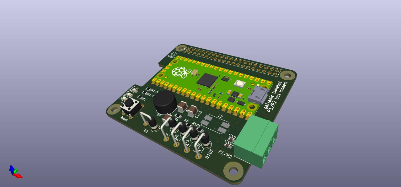
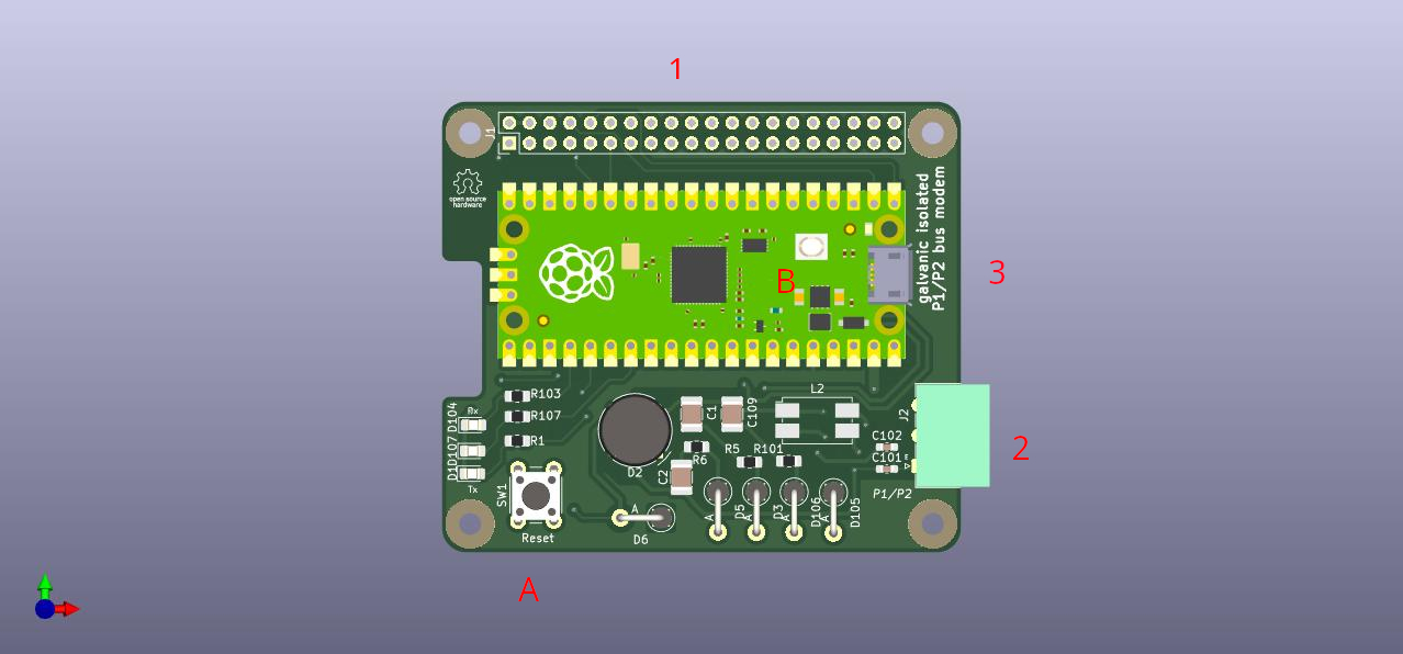
There are 3 connectors on the Pi hat:
Buttons:
A. Reset button
B. Boot-mode button
Hold button B and press button A to enter the Raspberry Pico USB bootloader.
THE OPEN SOURCE SOFTWARE/HARDWARE IN THIS PROJECT IS DISTRIBUTED
IN THE HOPE THAT IT WILL BE USEFUL, BUT WITHOUT ANY WARRANTY, WITHOUT
EVEN THE IMPLIED WARRANTY OF MERCHANTABILITY OR FITNESS FOR A
PARTICULAR PURPOSE.

The "Daikin P1/P2 Raspberry Pi hat" has been designed and tested with
Daikin's P1/P2 bus. You must not use this project to interface any
other electrical bus.| Qty | Value | Footprint | References |
|---|---|---|---|
| 8 | 10k | Resistor_SMD:R_0805_2012Metric_Pad1.20x1.40mm_HandSolder | R2, R3, R9, R10, R11, R12, R18, R19 |
| 4 | RPi_Hat:RPi_Hat_Mounting_Hole | , , , | |
| 4 | 100n | Capacitor_SMD:C_0805_2012Metric_Pad1.18x1.45mm_HandSolder | C5, C6, C8, C112 |
| 4 | ZF 5,6 | Diode_THT:D_DO-41_SOD81_P5.08mm_Vertical_AnodeUp | D3, D5, D105, D106 |
| 3 | 12k | Resistor_SMD:R_0805_2012Metric_Pad1.20x1.40mm_HandSolder | R17, R110, R116 |
| 3 | 1u | Capacitor_SMD:C_1210_3225Metric_Pad1.33x2.70mm_HandSolder | C7, C109, C110 |
| 3 | 470 | Resistor_SMD:R_0805_2012Metric_Pad1.20x1.40mm_HandSolder | R1, R103, R107 |
| 3 | LED | LED_SMD:LED_0805_2012Metric_Pad1.15x1.40mm_HandSolder | D1, D104, D107 |
| 2 | 1 | Resistor_SMD:R_0805_2012Metric_Pad1.20x1.40mm_HandSolder | R5, R6 |
| 2 | 18k | Resistor_SMD:R_0805_2012Metric_Pad1.20x1.40mm_HandSolder | R7, R8 |
| 2 | 1n | Capacitor_SMD:C_0603_1608Metric_Pad1.08x0.95mm_HandSolder | C101, C102 |
| 2 | 4k7 | Resistor_SMD:R_0805_2012Metric_Pad1.20x1.40mm_HandSolder | R104, R108 |
| 2 | 6k2 | Resistor_SMD:R_0805_2012Metric_Pad1.20x1.40mm_HandSolder | R109, R114 |
| 2 | 6u8 | Capacitor_SMD:C_1210_3225Metric_Pad1.33x2.70mm_HandSolder | C1, C2 |
| 2 | BLM21PG 331 | Inductor_SMD:L_0805_2012Metric_Pad1.15x1.40mm_HandSolder | L104, L105 |
| 2 | BSS123 | Package_TO_SOT_SMD:SOT-23 | Q1, Q2 |
| 1 | 100k | Resistor_SMD:R_0805_2012Metric_Pad1.20x1.40mm_HandSolder | R15 |
| 1 | 100p | Capacitor_SMD:C_0603_1608Metric_Pad1.08x0.95mm_HandSolder | C115 |
| 1 | 10u | Capacitor_SMD:C_1210_3225Metric_Pad1.33x2.70mm_HandSolder | C111 |
| 1 | 1u | Capacitor_SMD:C_0603_1608Metric_Pad1.08x0.95mm_HandSolder | C113 |
| 1 | 220k | Resistor_SMD:R_0805_2012Metric_Pad1.20x1.40mm_HandSolder | R16 |
| 1 | 220p | Capacitor_SMD:C_0805_2012Metric_Pad1.18x1.45mm_HandSolder | C4 |
| 1 | 2k2 | Resistor_SMD:R_0805_2012Metric_Pad1.20x1.40mm_HandSolder | R13 |
| 1 | 4,7 | Resistor_SMD:R_0805_2012Metric_Pad1.20x1.40mm_HandSolder | R102 |
| 1 | 4.7 | Resistor_SMD:R_0805_2012Metric_Pad1.20x1.40mm_HandSolder | R101 |
| 1 | 4u7 | Capacitor_SMD:C_1210_3225Metric_Pad1.33x2.70mm_HandSolder | C3 |
| 1 | 680u | Inductor_SMD:L_1210_3225Metric_Pad1.42x2.65mm_HandSolder | L1 |
| 1 | 76k | Resistor_SMD:R_0805_2012Metric_Pad1.20x1.40mm_HandSolder | R14 |
| 1 | B120-E3 | Diode_SMD:D_SMA | D4 |
| 1 | DNP | Resistor_SMD:R_0805_2012Metric_Pad1.20x1.40mm_HandSolder | R4 |
| 1 | D_Bridge_+A-A | Diode_THT:Diode_Bridge_Round_D9.0mm | D2 |
| 1 | LM4040DBZ-3 | Package_TO_SOT_SMD:SOT-23 | U1 |
| 1 | L_Coupled_1243 | B82790C0:L_CommonMode_TDK_B82790C0 | L2 |
| 1 | PC MC_1,5_2-G-3.81 | Connector_Phoenix_MC:PhoenixContact_MC_1,5_3-G-3.81_1x03_P3.81mm_Horizontal | J2 |
| 1 | Pico | Pico:RPi_Pico_SMD_TH | U3 |
| 1 | Raspberry_Pi_2_3 | Connector_PinHeader_2.54mm:PinHeader_2x20_P2.54mm_Vertical | J1 |
| 1 | SM6T 36A STM | Diode_SMD:D_SMB | D101 |
| 1 | SW_Push | Button_Switch_THT:SW_PUSH_6mm_H5mm | SW1 |
| 1 | TS4990 | Package_SO:SOIC-8_3.9x4.9mm_P1.27mm | U103 |
| 1 | ZF 15 | Diode_THT:D_DO-41_SOD81_P5.08mm_Vertical_AnodeUp | D6 |
pilerks1/ECE-445L-Final-Project
forked from ece445l_spring_2025-ece-445l-lab-7-and-10

nikodem-czechowski/OpenSPAD
My implementation of the OpenSPAD based on the design by GaudiLabs


TilenTinta/ReflowOven_controller
An open source controller for converting kitchen toaster oven to reflow oven

alanmimms/nexrig
A ham oriented SSB exciter for 160m-10m that uses a PC or Raspberry Pi USB host as UI and DSP.

Afligh8/FlightController
A simple Plug and Play FLight Controller for Wings. Supports two motors with ESC, 6 PWM pins, SPI, I2C and Serials. Also 6 ports for servos and extra GPIO pins for debug and freelance.

ChristosChristoforou/Keyboard
Mechanical Keyboard PCB with four layers, two rotary encoder switches and 78 cherry-mx(pcb-mount) switches.
It measures 65 × 56.5 mm and has 2 copper layers, 1.6 mm thick.
72 parts, built around the TS4990IDT, BSS123 and B120-E3. The full list of its parts is on this page, with links to each part's symbol and footprint where PCBKit's library has them.
From the siro20/P1P2_HBS_USBCdc_Modem repository on GitHub, at the commit this page was made from: the board is kicad/p1p2_pi_hat.kicad_pcb and its schematic kicad/p1p2_pi_hat.kicad_sch. PCBKit opens the board in the browser, with nothing to install.
Its repository states no licence, so its author keeps all rights: ask siro20 before reusing the design.