2 layers107 × 64 mm
 shyver/sensor-node
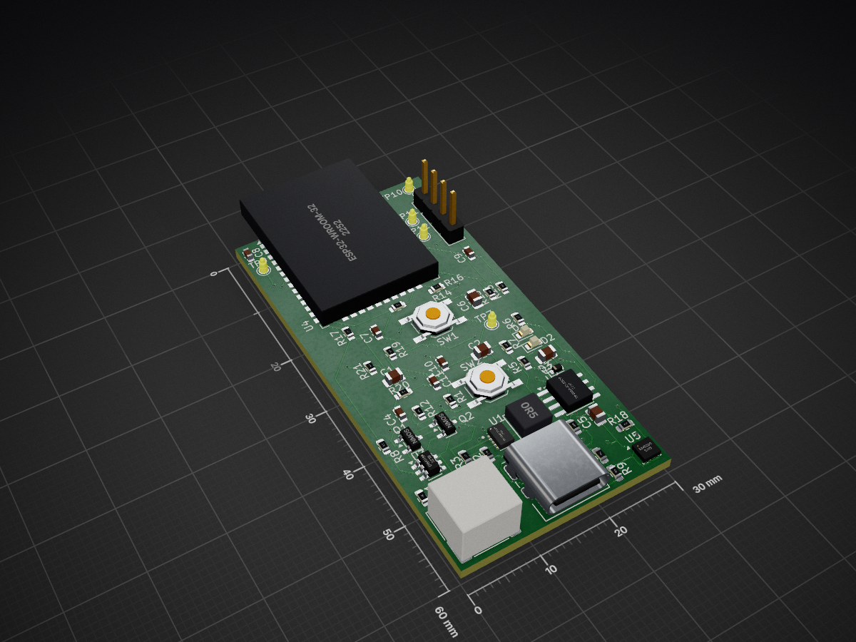
This project is a compact, battery-powered environmental monitoring device built around the ESP32. It is designed to measure temperature, humidity, and atmospheric pressure, and transmit data wirelessly over Wi-Fi.
Sensor node kicad is an open-source printed circuit board by shyver, from the shyver/sensor-node repository on GitHub, published under the MIT licence. It is a 2-layer board of 30 × 60 mm with 53 parts on 61 nets, routed with 420 tracks and 33 vias.
It is built around the ESP32-WROOM-32E, BME280 and TPS63802DLAR, with the DW01A and TP4056-42-ESOP8 among its other parts. Its parts include 21 resistors, 11 capacitors, 5 ICs, 3 diodes and 3 connectors. It belongs with the home automation and IoT and sensors and measurement boards and the ESP32 boards of this library.


This project is a compact, battery-powered environmental monitoring device built around the ESP32. It is designed to measure temperature, humidity, and atmospheric pressure, and transmit data wirelessly over Wi-Fi.
The system integrates power management, battery charging, sensing, and communication into a single PCB, making it suitable for IoT applications and embedded product prototyping.
The system is composed of the following main subsystems:
USB-C → Charger → Battery → Regulator → ESP32 → Sensor (I2C)ESP32 Module Selection Used a pre-certified ESP32 module to simplify RF design and ensure reliable Wi-Fi performance.
Battery-Powered Architecture Designed around a single-cell Li-Po battery for portability and real-world IoT use cases.
Power Regulation Strategy Implemented a regulated 3.3V rail to ensure stable operation during ESP32 current spikes.
USB-C Power-Only Configuration USB-C connector used strictly for power input, avoiding unnecessary USB data complexity.
I2C Sensor Interface Selected a digital sensor with I2C to minimize pin usage and simplify routing.
Hardware design and layout by Abdelwahed Eloued
This project is open-source and available under the MIT License.
| Qty | Value | Footprint | References |
|---|---|---|---|
| 6 | 0.1µF | Capacitor_SMD:C_0603_1608Metric | C4, C7, C8, C9, C10, C11 |
| 6 | 10k | Resistor_SMD:R_0603_1608Metric | R12, R13, R14, R15, R16, R17 |
| 3 | 100k | Resistor_SMD:R_0603_1608Metric | R1, R20, R21 |
| 3 | 10µF | Capacitor_SMD:C_0805_2012Metric | C3, C5, C6 |
| 3 | 1k | Resistor_SMD:R_0603_1608Metric | R5, R6, R8 |
| 2 | 22µF | Capacitor_SMD:C_0805_2012Metric | C1, C2 |
| 2 | 4.7k | Resistor_SMD:R_0603_1608Metric | R18, R19 |
| 2 | 5.1k | Resistor_SMD:R_0603_1608Metric | R9, R10 |
| 2 | NMOS | Package_TO_SOT_SMD:SOT-23 | Q1, Q2 |
| 2 | SW_Push | Button_Switch_SMD:SW_SPST_TL3342 | SW1, SW2 |
| 1 | 0.4 | Resistor_SMD:R_0603_1608Metric | R4 |
| 1 | 100 | Resistor_SMD:R_0603_1608Metric | R11 |
| 1 | 2.4k | Resistor_SMD:R_0603_1608Metric | R7 |
| 1 | 3V3 | TestPoint:TestPoint_Pad_D1.5mm | TP7 |
| 1 | 470nH | ul_XFL4015-471MEC:IND_XFL4015_COC-M | L1 |
| 1 | 511k | Resistor_SMD:R_0603_1608Metric | R2 |
| 1 | 91k | Resistor_SMD:R_0603_1608Metric | R3 |
| 1 | BME280 | Package_LGA:Bosch_LGA-8_2.5x2.5mm_P0.65mm_ClockwisePinNumbering | U5 |
| 1 | Conn_01x02 | Connector_JST:JST_PH_S2B-PH-SM4-TB_1x02-1MP_P2.00mm_Horizontal | J2 |
| 1 | Conn_01x04 | Connector_PinHeader_2.54mm:PinHeader_1x04_P2.54mm_Vertical | J3 |
| 1 | DW01A | Package_TO_SOT_SMD:SOT-23-6 | U3 |
| 1 | EN | TestPoint:TestPoint_Pad_D1.5mm | TP9 |
| 1 | ESD5Zxx | Diode_SMD:D_SOD-523 | D3 |
| 1 | ESP32-WROOM-32E | RF_Module:ESP32-WROOM-32D | U4 |
| 1 | GREEN | LED_SMD:LED_0603_1608Metric | D2 |
| 1 | IO0 | TestPoint:TestPoint_Pad_D1.5mm | TP10 |
| 1 | RED | LED_SMD:LED_0603_1608Metric | D1 |
| 1 | RX0 | TestPoint:TestPoint_Pad_D1.5mm | TP12 |
| 1 | TP4056-42-ESOP8 | Package_SO:SOIC-8-1EP_3.9x4.9mm_P1.27mm_EP2.41x3.3mm_ThermalVias | U2 |
| 1 | TPS63802DLAR | TPS63802DLAR:VREG_TPS63802DLAR | U1 |
| 1 | TX0 | TestPoint:TestPoint_Pad_D1.5mm | TP11 |
| 1 | USB_C_Receptacle_USB2.0_14P | Connector_USB:USB_C_Receptacle_GCT_USB4085 | J1 |
It measures 30 × 60 mm and has 2 copper layers, 1.6 mm thick.
53 parts, built around the ESP32-WROOM-32E, BME280, TPS63802DLAR and DW01A. The full list of its parts is on this page, with links to each part's symbol and footprint where PCBKit's library has them.
From the shyver/sensor-node repository on GitHub, at the commit this page was made from: the board is kicad/sensor_node_kicad.kicad_pcb and its schematic kicad/power.kicad_sch. PCBKit opens the board in the browser, with nothing to install.
Its repository publishes it under the MIT licence: you may reuse it on that licence's terms (keep the author's notice, and for a copyleft licence share your changes alike).

KazimGL/ESP32-PowerIoT-DevBoard
ESP32 battery-powered IoT dev board with Li-ion charging, protection, and sensor support — designed in KiCad

Oluwaseunemme/ESP32-BLE-Multi-Meter
A custom ESP32-based digital multimeter capable of measuring DC voltage, resistance, continuity, diode forward voltage, and capacitance, with measurement results transmitted wirelessly to a Flutter mobile application…

dharaneesh-m-oss/lorawatch_pcb
Compact LoRa-based Wearable IoT PCB using ESP32 with GPS, MPU6050, BME280, USB-C charging, and battery management designed in KiCad.


Salma-lotfy-Wazery/esp32-battery-powered-iot-node
Custom 2-layer PCB designed in KiCad featuring ESP32, integrated LiPo charging (TP4056), USB-C power delivery, and sensor telemetry.

unixvoid/SquidTX-Nano-ELRS
Nano ELRS TX designed for the DIY 2400 E28 ELRS target. Includes internal boost converter 1.3v-5.5v input
