
2 layers89.6 × 79 mm
TDR 5351 core
MR-DOS/TDR_diploma_thesis
Time domain reflectometer. Includes Hardware, firmware and GUI in Octave. Also a diploma thesis.
199 parts33GPL-3.0

 sh123/nano_power_meter30
Dual channel Arduino Nano milliwatt power meter for HF/VHF/UHF/SHF bands
Power meter is an open-source printed circuit board by sh123, from the sh123/nano_power_meter repository on GitHub, published under the GPL-2.0 licence. It is a 2-layer board of 44.5 × 43.2 mm with 23 parts on 40 nets, routed with 69 tracks and 73 vias.
It is built around the AD8307AN. Its parts include 10 capacitors, 5 resistors, 4 connectors, 2 ICs and 1 inductor. It belongs with the radio and wireless and sensors and measurement boards and the AVR (ATmega, ATtiny) boards of this library.
Dual channel Arduino Nano RF milliwatt power meter for HF/VHF/UHF/SHF bands. Can be used for power measurement, different RF equipment troubleshooting, RF leakage search and antenna radiation/gain measurements and comparison.
This project is Arduino Nano clone of W1GHZ power meter adopted for use with Arduino Nano and SSD1307 OLED screen. Read more details at http://www.w1ghz.org/new/portable_powermeter.pdf.
Unlike original meter, which is just an indicator, this device shows precise dBm values and could be calibrated, calibration table is stored in the sketch. Moreover, device takes maximum RF power value during 1 second interval, which allows signal duration measurements down to 1 ms and marks maximum value during 1 minute interval on the bar.
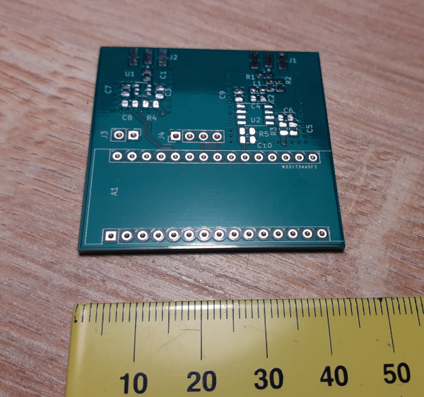
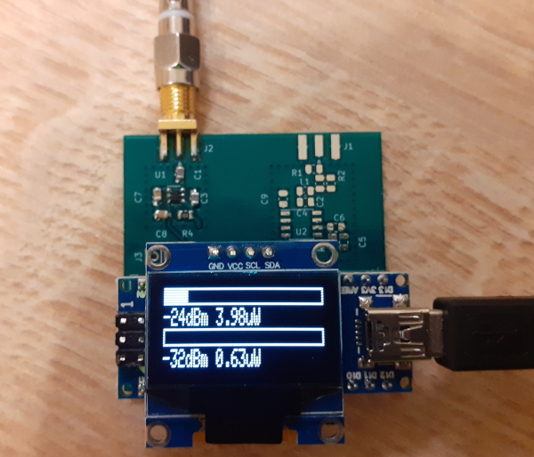
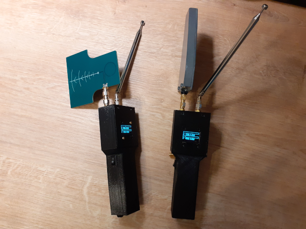
User platformio to build and upload.
Sucessfully shows power values for various ISM signals, such as 5 GHz, 2.4 GHz WiFi, Bluetooth, 433/868 MHz ISM devices at close range and amateur radio transmissions at HF.
At SHF band good sensitivity and results are achieved when using cheap Vivaldi antenna.
At HF/VHF/UHF telescopic antenna performs well enough. For close board inspection EM probes could be used.
Also, additional shield could be helpful.
Device must be powered from the battery only, powering from PC USB will cause PC USB RFI and other noise to be measured by the device.
Signals with larger than +20 dBm levels could be measured with additional external attenuator.
| Qty | Value | Footprint | References |
|---|---|---|---|
| 4 | 0.1uF | Capacitor_SMD:C_0805_2012Metric | C3, C7, C8, C10 |
| 3 | R | Resistor_SMD:R_0805_2012Metric | R2, R3, R5 |
| 2 | C | Capacitor_SMD:C_0805_2012Metric | C6, C9 |
| 1 | .01uF | Capacitor_SMD:C_0805_2012Metric | C4 |
| 1 | 100pF | Capacitor_SMD:C_0805_2012Metric | C5 |
| 1 | 10k | Resistor_SMD:R_0805_2012Metric | R4 |
| 1 | 15pF | Capacitor_SMD:C_0805_2012Metric | C2 |
| 1 | 51 | Resistor_SMD:R_0805_2012Metric | R1 |
| 1 | 8.2pF | Capacitor_SMD:C_0805_2012Metric | C1 |
| 1 | Arduino_Nano_v3.x | Module:Arduino_Nano | A1 |
| 1 | Conn_01x02 | Connector_PinHeader_2.54mm:PinHeader_1x02_P2.54mm_Vertical | J3 |
| 1 | Conn_01x04 | Connector_PinHeader_2.54mm:PinHeader_1x04_P2.54mm_Vertical | J4 |
| 1 | L | Inductor_SMD:L_0805_2012Metric | L1 |
| 1 | RF_SHF | Connector_Coaxial:SMA_Samtec_SMA-J-P-H-ST-EM1_EdgeMount | J2 |
| 1 | RF_UHF | Connector_Coaxial:SMA_Samtec_SMA-J-P-H-ST-EM1_EdgeMount | J1 |
| 1 | ad8307 | Package_SO:SOIC-8_3.9x4.9mm_P1.27mm | U2 |
| 1 | ltc5508 | Package_SO:TSOP-6_1.65x3.05mm_P0.95mm | U1 |
MR-DOS/TDR_diploma_thesis
Time domain reflectometer. Includes Hardware, firmware and GUI in Octave. Also a diploma thesis.


paretech/Watson
PCB layout and test results for a simple high dynamic range power meter based on the Analog Devices AD8307 Logarithmic Amplifier.

MR-DOS/generator_5351_rect_sine
Rectangular and sine generator with Si5351 working up to 200 MHz

SmittyHalibut/HF-QRP-ServiceMonitor
A set of testing gear for your HF QRP radios.


It measures 44.5 × 43.2 mm and has 2 copper layers, 1.6 mm thick.
23 parts, built around the AD8307AN. The full list of its parts is on this page, with links to each part's symbol and footprint where PCBKit's library has them.
From the sh123/nano_power_meter repository on GitHub, at the commit this page was made from: the board is extras/schematics/power_meter.kicad_pcb and its schematic extras/schematics/power_meter.kicad_sch. PCBKit opens the board in the browser, with nothing to install.
Its repository publishes it under the GPL-2.0 licence: you may reuse it on that licence's terms (keep the author's notice, and for a copyleft licence share your changes alike).