2 layers72.4 × 49.5 mm
 dmsmccann/Spectrum-Analyzer2
Based on design by W7ZOI in 1998 QST
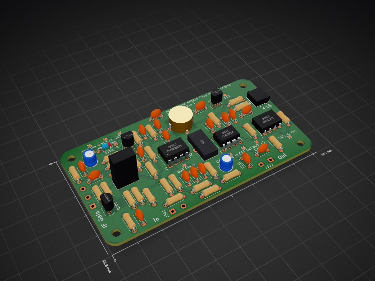
If and log amp is an open-source printed circuit board by dmsmccann, from the dmsmccann/Spectrum-Analyzer repository on GitHub. It is a 2-layer board of 91.7 × 48.8 mm with 75 parts on 42 nets, routed with 343 tracks and 0 vias.
It is built around the AD603AQ, AD8307AN and CA3140. Its parts include 28 resistors, 21 capacitors, 5 ICs, 4 connectors and 1 diode. It belongs with the audio and music boards of this library.


This repository contains a complete KiCad implementation of the famous W7ZOI Spectrum Analyzer design, originally published in QST magazine. The W7ZOI spectrum analyzer is a well-regarded amateur radio test instrument design that provides a cost-effective solution for RF spectrum analysis.
The W7ZOI Spectrum Analyzer is a superheterodyne spectrum analyzer designed for amateur radio applications. It provides frequency analysis capabilities across the HF and VHF bands, making it an invaluable tool for antenna analysis, filter characterization, and general RF measurements.
├── hierarchical-schematic/     # Main hierarchical schematic files
├── 110mhz/                    # 110 MHz filter module
├── 15v-supply/                # Power supply module
├── 2db-div/                   # 2dB divider module
├── 2ndmixer-2ndlo/           # 2nd mixer and LO module
├── 70mhz-lpf/                # 70 MHz low-pass filter
├── 7mhz-crystal-oscillator/  # 7 MHz crystal oscillator
├── if-and-log-amp/           # IF and log amplifier
├── resolution-filters/        # Resolution filter bank
├── timebase/                 # Timebase generation
├── tracking-generator/        # Tracking generator module
├── vco-1stmixer/             # VCO and 1st mixer
├── literature/               # Reference documentation and articles
├── images/                   # Project images and diagrams
└── experimental-data/ # Test data and measurementsThe literature/ directory contains extensive reference material including:
hierarchical-schematic/W7ZOI Spectrum Analyzer.kicad_proThis implementation includes several improvements over the original design:
Refer to the documentation in the literature/ directory for detailed construction information. The original QST articles provide comprehensive building instructions, alignment procedures, and performance specifications.
Contributions are welcome! Please feel free to submit issues, improvements, or additional documentation. When contributing:
This project is based on the original W7ZOI design published in QST magazine. Please respect copyright and amateur radio regulations in your use of these designs.
literature/ directoryThis is an amateur radio project intended for educational and experimental use. Please ensure compliance with your local amateur radio regulations.
| Qty | Value | Footprint | References |
|---|---|---|---|
| 11 | .1u | Capacitor_THT:C_Disc_D5.0mm_W2.5mm_P5.00mm | C301, C302, C303, C306, C307, C308, C310, C316, C317, C318, C321 |
| 4 | 10 | Resistor_THT:R_Axial_DIN0207_L6.3mm_D2.5mm_P7.62mm_Horizontal | R318, R322, R323, R328 |
| 4 | 2.2k | Resistor_THT:R_Axial_DIN0207_L6.3mm_D2.5mm_P7.62mm_Horizontal | R308, R309, R314, R326 |
| 4 | MountingHole | MountingHole:MountingHole_3.2mm_M3 | H301, H302, H303, H304 |
| 3 | 100 | Resistor_THT:R_Axial_DIN0207_L6.3mm_D2.5mm_P7.62mm_Horizontal | R305, R306, R307 |
| 3 | 1k | Resistor_THT:R_Axial_DIN0207_L6.3mm_D2.5mm_P7.62mm_Horizontal | R313, R317, R327 |
| 2 | 5.6p | Capacitor_THT:C_Disc_D5.0mm_W2.5mm_P5.00mm | C312, C322 |
| 2 | 51 | Resistor_THT:R_Axial_DIN0207_L6.3mm_D2.5mm_P7.62mm_Horizontal | R310, R324 |
| 2 | 680 | Resistor_THT:R_Axial_DIN0207_L6.3mm_D2.5mm_P7.62mm_Horizontal | R311, R325 |
| 1 | +15 | TestPoint:TestPoint_Pad_1.0x1.0mm | TP307 |
| 1 | +15 In | spectrum analyzer:691103110002 | J303 |
| 1 | .001u | Capacitor_THT:C_Disc_D5.0mm_W2.5mm_P5.00mm | C320 |
| 1 | .01u | Capacitor_THT:C_Disc_D5.0mm_W2.5mm_P5.00mm | C304 |
| 1 | .22u | Capacitor_THT:C_Disc_D5.0mm_W2.5mm_P5.00mm | C319 |
| 1 | 1.05u | Inductor_THT:L_Toroid_Vertical_L13.0mm_W6.5mm_P5.60mm | L301 |
| 1 | 1.5k | Resistor_THT:R_Axial_DIN0207_L6.3mm_D2.5mm_P7.62mm_Horizontal | R320 |
| 1 | 100u | Capacitor_THT:CP_Radial_D5.0mm_P2.50mm | C305 |
| 1 | 10k | Resistor_THT:R_Axial_DIN0207_L6.3mm_D2.5mm_P7.62mm_Horizontal | R304 |
| 1 | 18p | Capacitor_THT:C_Disc_D5.0mm_W2.5mm_P5.00mm | C309 |
| 1 | 1N4148 | Diode_THT:D_DO-35_SOD27_P7.62mm_Horizontal | D301 |
| 1 | 220 | Resistor_THT:R_Axial_DIN0207_L6.3mm_D2.5mm_P7.62mm_Horizontal | R319 |
| 1 | 220p | Capacitor_THT:C_Disc_D5.0mm_W2.5mm_P5.00mm | C314 |
| 1 | 22u | Capacitor_THT:CP_Radial_D5.0mm_P2.50mm | C311 |
| 1 | 2N3904 | Package_TO_SOT_THT:TO-92_Inline | Q301 |
| 1 | 2k | Resistor_THT:R_Axial_DIN0207_L6.3mm_D2.5mm_P7.62mm_Horizontal | R303 |
| 1 | 4.3k | Resistor_THT:R_Axial_DIN0207_L6.3mm_D2.5mm_P7.62mm_Horizontal | R316 |
| 1 | 47 | Resistor_THT:R_Axial_DIN0207_L6.3mm_D2.5mm_P7.62mm_Horizontal | R301 |
| 1 | 470 | Resistor_THT:R_Axial_DIN0207_L6.3mm_D2.5mm_P7.62mm_Horizontal | R302 |
| 1 | 5-65pf | spectrum analyzer:BFC280831659 | C313 |
| 1 | 5.6k | Resistor_THT:R_Axial_DIN0207_L6.3mm_D2.5mm_P7.62mm_Horizontal | R315 |
| 1 | 510 | Resistor_THT:R_Axial_DIN0207_L6.3mm_D2.5mm_P7.62mm_Horizontal | R312 |
| 1 | 603 In | TestPoint:TestPoint_Pad_1.0x1.0mm | TP301 |
| 1 | 603 Out | TestPoint:TestPoint_Pad_1.0x1.0mm | TP304 |
| 1 | 603 Pin 4 | TestPoint:TestPoint_Pad_1.0x1.0mm | TP302 |
| 1 | 603 Pin 8 | TestPoint:TestPoint_Pad_1.0x1.0mm | TP303 |
| 1 | 803 +5 | TestPoint:TestPoint_Pad_1.0x1.0mm | TP309 |
| 1 | 803 In | TestPoint:TestPoint_Pad_1.0x1.0mm | TP305 |
| 1 | 803 Out | TestPoint:TestPoint_Pad_1.0x1.0mm | TP306 |
| 1 | 82 | Resistor_THT:R_Axial_DIN0207_L6.3mm_D2.5mm_P7.62mm_Horizontal | R321 |
| 1 | AD603AQ | spectrum analyzer:AD603AQ | U301 |
| 1 | AD8307 | spectrum analyzer:AD8307AN | U302 |
| 1 | CA3140 | spectrum analyzer:CA3140EZ | U303 |
| 1 | CA3140 Out | TestPoint:TestPoint_Pad_1.0x1.0mm | TP308 |
| 1 | Coax | Connector_Wire:SolderWire-0.5sqmm_1x02_P4.6mm_D0.9mm_OD2.1mm | J301 |
| 1 | Conn_01x03 | Connector_Wire:SolderWire-0.5sqmm_1x03_P4.6mm_D0.9mm_OD2.1mm | J304 |
| 1 | Conn_Coaxial | Connector_Wire:SolderWire-0.5sqmm_1x02_P4.6mm_D0.9mm_OD2.1mm | J302 |
| 1 | FT37-43 8:2 t | spectrum analyzer:Transformer Vertical 1P 1S | T301 |
| 1 | L78L05_TO92 | Package_TO_SOT_THT:TO-92_Inline | U305 |
| 1 | LM317L_TO92 | Package_TO_SOT_THT:TO-92_Inline | U304 |


benishor/w7zoi-sa-ad8307-log-amp
Kicad files for the new AD8307 log amp for W7ZOI spectrum analyzer.

MR-DOS/TDR_diploma_thesis
Time domain reflectometer. Includes Hardware, firmware and GUI in Octave. Also a diploma thesis.

sh123/nano_power_meter
Dual channel Arduino Nano milliwatt power meter for HF/VHF/UHF/SHF bands


paretech/Watson
PCB layout and test results for a simple high dynamic range power meter based on the Analog Devices AD8307 Logarithmic Amplifier.

MR-DOS/generator_5351_rect_sine
Rectangular and sine generator with Si5351 working up to 200 MHz

SmittyHalibut/HF-QRP-ServiceMonitor
A set of testing gear for your HF QRP radios.
It measures 91.7 × 48.8 mm and has 2 copper layers, 1.6 mm thick.
75 parts, built around the AD603AQ, AD8307AN and CA3140. The full list of its parts is on this page, with links to each part's symbol and footprint where PCBKit's library has them.
From the dmsmccann/Spectrum-Analyzer repository on GitHub, at the commit this page was made from: the board is if-and-log-amp/if-and-log-amp/if-and-log-amp.kicad_pcb and its schematic 110mhz/110mhz.kicad_sch. PCBKit opens the board in the browser, with nothing to install.
Its repository states no licence, so its author keeps all rights: ask dmsmccann before reusing the design.