
2 layers373.4 × 34.5 mm

 SendhanS/QRE1113-7-Sensor-array
This repository contains the design files for a 7-channel QRE1113-based infrared line sensor array intended for line follower robots. The PCB uses a slight arc layout on a planar board, operates at a 5 V supply, and provides individual analog outputs for each sensor, suitable for high-speed line tracking and control algorithms.
QRE1113-Array is an open-source printed circuit board by SendhanS, from the SendhanS/QRE1113-7-Sensor-array repository on GitHub, published under the MIT licence. It is a 2-layer board of 128.3 × 17.5 mm with 23 parts on 16 nets, routed with 116 tracks and 0 vias.
It is built around the QRE1113. Its parts include 14 resistors, 7 ICs and 1 connector. It belongs with the sensors and measurement and robots and motor control boards of this library.
This repository contains the complete schematic and PCB design files for a 7-channel QRE1113-based infrared reflectance sensor array intended for competitive line follower robots.
The design operates on a 5 V supply and provides individual analog outputs for each sensor, enabling precise line position estimation using ADC-based processing and PID control algorithms. The sensors are arranged in a slight arc geometry on a planar PCB, improving curve anticipation and stability at higher speeds compared to a straight-line array.
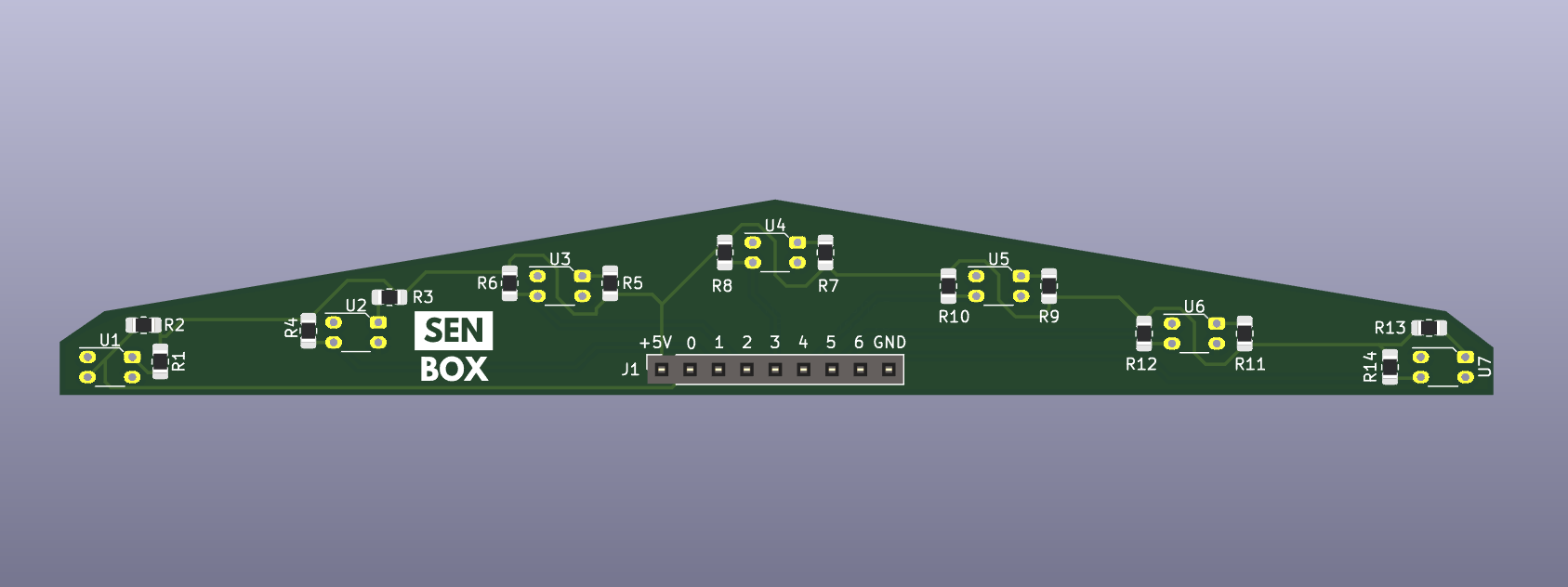
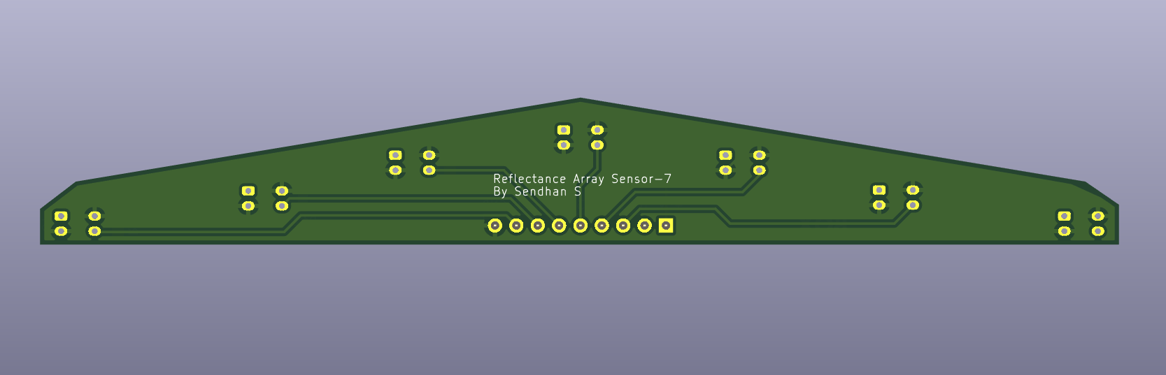
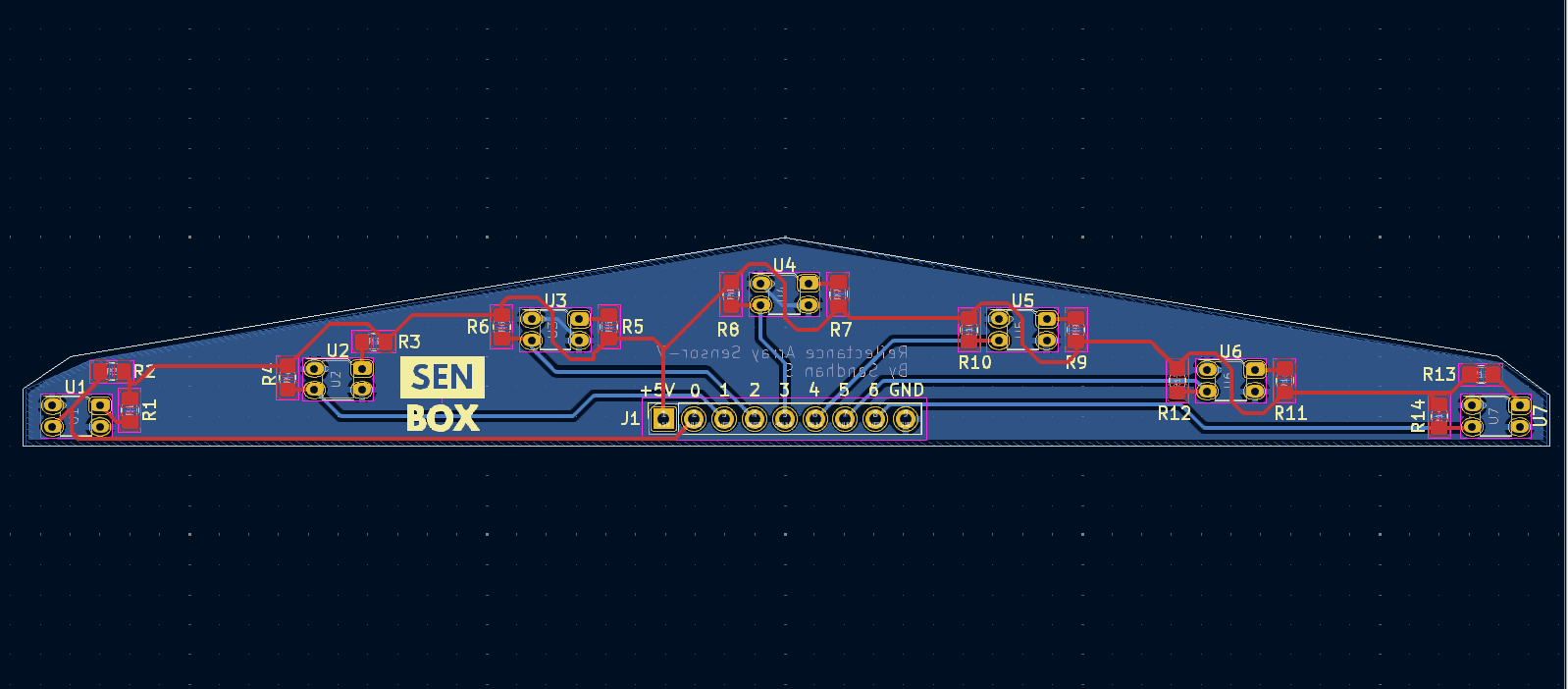
This project is intended for learning, experimentation, and portfolio demonstration.
| Qty | Value | Footprint | References |
|---|---|---|---|
| 7 | 100 | Resistor_SMD:R_0805_2012Metric_Pad1.20x1.40mm_HandSolder | R1, R3, R5, R7, R9, R11, R13 |
| 7 | 10k | Resistor_SMD:R_0805_2012Metric_Pad1.20x1.40mm_HandSolder | R2, R4, R6, R8, R10, R12, R14 |
| 7 | QRE1113 | OptoDevice:OnSemi_CASE100AQ | U1, U2, U3, U4, U5, U6, U7 |
| 1 | Conn_01x09_Socket | Connector_PinSocket_2.54mm:PinSocket_1x09_P2.54mm_Vertical | J1 |
| 1 | LOGO | LOGO | G*** |
It measures 128.3 × 17.5 mm and has 2 copper layers, 1.6 mm thick.
23 parts, built around the QRE1113. The full list of its parts is on this page, with links to each part's symbol and footprint where PCBKit's library has them.
From the SendhanS/QRE1113-7-Sensor-array repository on GitHub, at the commit this page was made from: the board is Project_files/QRE1113-Array.kicad_pcb and its schematic Project_files/QRE1113-Array.kicad_sch. PCBKit opens the board in the browser, with nothing to install.
Its repository publishes it under the MIT licence: you may reuse it on that licence's terms (keep the author's notice, and for a copyleft licence share your changes alike).

fwachsmuth/Filmkorn-Raw-Scanner
The Filmkorn Raw Scanner, turning 8mm and 16mm films into lossless 12-bit CinemaDNG


OPRobots/Yokozunita
Robot minisumo con PCBs, motores fingertech, plomo fundido y stepUp.

project-neon/Esguicho
Neste repositório temos os principais arquivos que usamos para os 3 capítulos, Eletrônica, Mecânica e Software. Segue abaixo uma lista do que temos em cada uma das pastas:

vorlaxen-labs/AratMicro
High-performance, open-source micromouse robot platform built for Robosam and MEB Robot (Ministry of National Education Robotics Competition, Turkey).
