2 layers
Stlinkv2
dltech/stlinkv2
ST-link V2 schematic and PCB in kiCAD with initial firmware through UART
60 parts23
 scrapcomputing/SerialMouseBlasterPCB13
Serial Mouse Blaster PCB
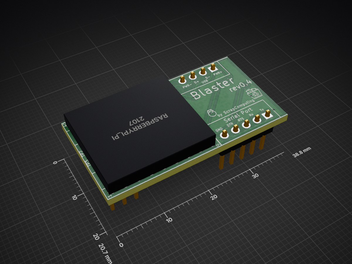
SerialMouseBlasterPCB is an open-source printed circuit board by scrapcomputing, from the scrapcomputing/SerialMouseBlasterPCB repository on GitHub, published under the GPL-2.0 licence. It is a 2-layer board of 38.8 × 20.7 mm with 29 parts on 24 nets, routed with 322 tracks and 18 vias.
It is built around the LM358, BAS40-04 and BZX84-C5V1, with the MMBTA92 among its other parts. Its parts include 8 resistors, 7 capacitors, 7 diodes, 3 ICs and 3 connectors. It belongs with the interfaces and adapters boards and the RP2040 boards of this library.


A PCB used for modding a modern optical USB mouse and converting it into a Serial mouse.
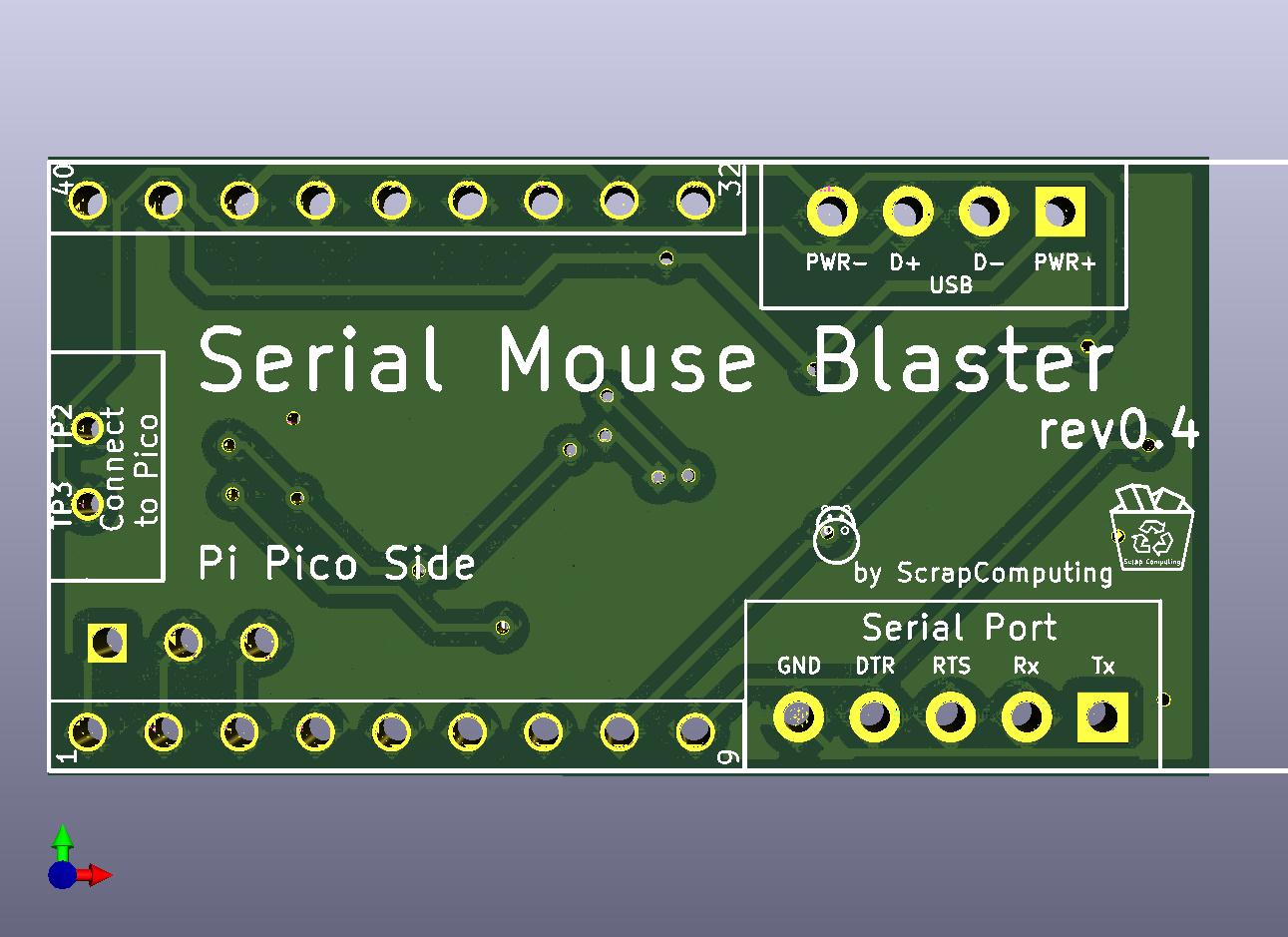
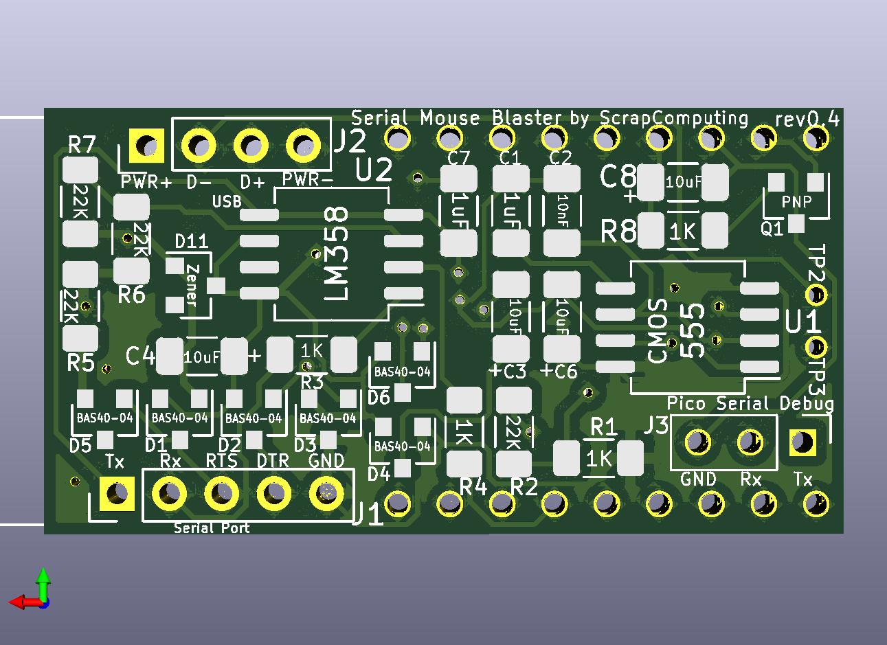
This is based on a Raspberry Pi Pico running the SerialMouseBlaster firmware.
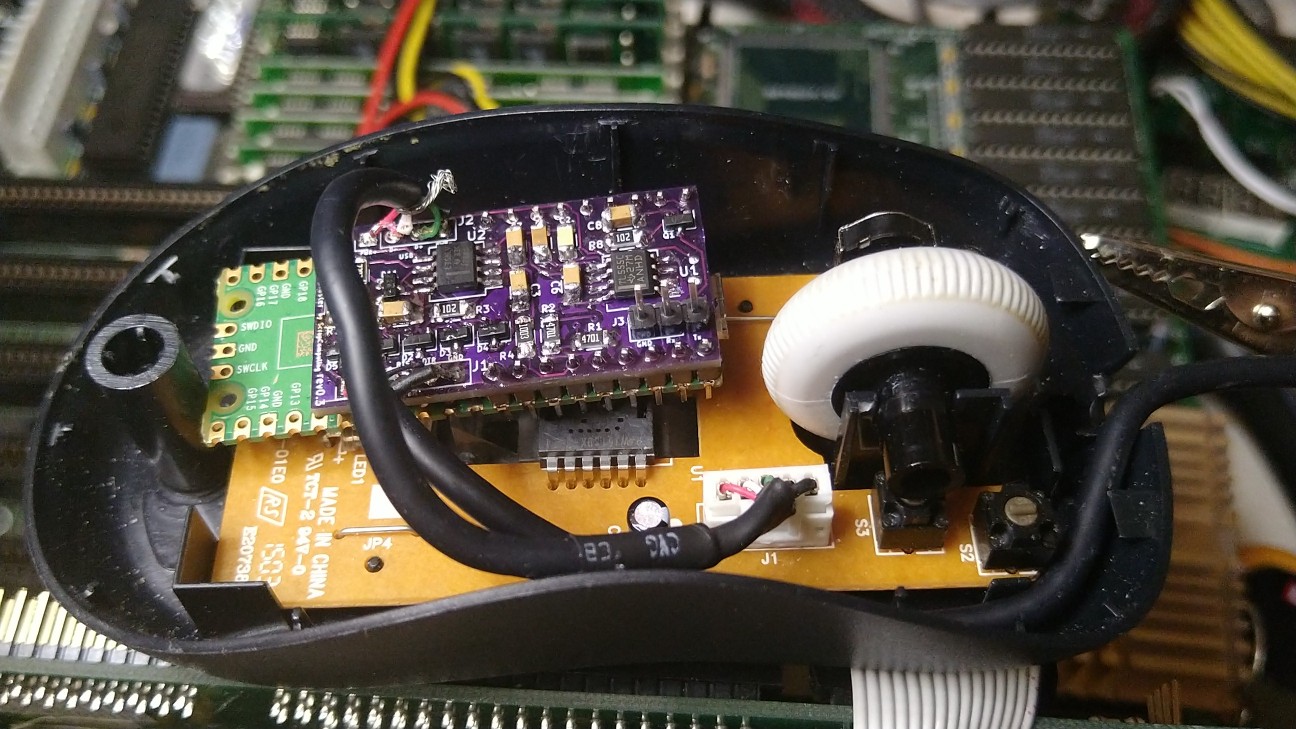
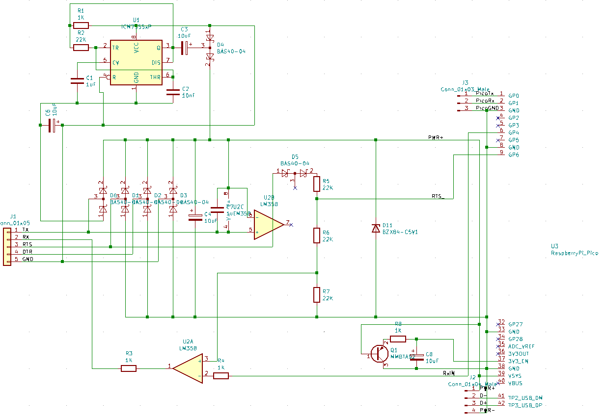
The SerialMouseBlaster has two jobs:
The end result is an adapter board that converts a USB optical mouse to a serial one with no external power.
Short answer: You have to measure it first, but a relatively modern mouse with a < 5mA consumption on idle should work after the resistor mod.
The serial port provides very little power, up to 15mA in total at 5V. Currently the Pico consumes about half of it and the rest of the circuitry about another 15-20%. So the we only have about 5mA to spare for the USB mouse. So a good mouse candidate is one that consumes up to 5mA.
The problem though is that most USB optical mice consume much more than this. But most of the power is usually consumed by the LED (usually red) which illuminates the surface. Luckily the mouse camera can still work even with a much dimmer LED. So we can reduce the power consumption by adding a resistor in series with the LED. A good resistor values is usually around 1K Ohms. Some mice may even work with higher resistor values, but beyond some value the camera can no longer see the surface and the mouse will not register mouse movement. So for best results use the largest resistor value you can without affecting the functionality of the mouse.
Some mice already have an SMD resistor in-series with the LED (see image below of the Microsoft Basic Optical Mouse v2.0). This resistor is usually a very low value. For a cleaner mod, you can simply replace this resistor with another SMD one of much higher value.
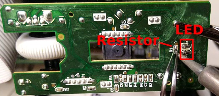
You can usually tell if a mouse is low-power enough by simply measuring its idle current, without the resistor mod. If it is under 5mA, then it has a good chance of working well with a mod. If not, then the chances are that it will consume too much power even with the mod.
Please note that a typical optical USB mouse will consume several times higher power when you move it as the LED becomes a lot brighter than when it is not moving.
| Brand | Model | Idle Current | Max Current | Mod Resistor | Modded Idle | Modded Max |
|---|---|---|---|---|---|---|
| Microsoft | Basic Optical Mouse v2.0 | 3.5mA | ~15mA | 2.2K | 2.7mA | 5.4mA |
| Logitech | B100 | 8.4mA | ~24mA | 1K | 6.4mA | 8.6mA |
| Brand | Model | Idle Current | Max Current |
|---|---|---|---|
| Dell | M-UVDEL1 | 20.7mA | 59.2mA |
| Apple | A1152 | 26.7mA | 69.7mA |
| Microsoft | Basic Optical Mouse | 29.4mA | 54.3mA |
| Microsoft | Wheel Mouse Optical 1.1A | 44.1mA | 61.4mA |
Note Please help me populate these tables. Feel free to reach out or send out a pull request if you measured your mouse and you want to share your numbers.
The serial port does not provide power. So any device connected to it either needs to be powered externally, or try to use power from the logic output pins. There are 3 output pins: TXD, DTR and RTS. These can usually provide up to about 5mA at 5V.
The SerialMouseBlaster uses power from all three pins. When the mouse driver initializes the serial port, DTR and RTS are high (about +10V), while TXD is low (about -10V). In order to get power from TXD, it uses a 7555 timer chip as a voltage doubler, which outputs positive voltage.
Level-shifting is done with an LM385 Op Amp which consumes only 1.5mA, as opposed to using a MAX3232, which according to my measurements consumed more than 5mA.
| Pin | Name | Direction | Description |
|---|---|---|---|
| 1 | CD | IN | Carrier Detect |
| 2 | RXD | IN | Receive Data |
| 3 | TXD | OUT | Transmit Data |
| 4 | DTR | OUT | Data Terminal Ready |
| 5 | GND | Ground | |
| 6 | DSR | IN | Data Set Ready |
| 7 | RTS | OUT | Request To Send |
| 8 | CTS | IN | Clear To Send |
| 9 | IR | IN | Ring Indicator |
Female connector looking at the holes:
 -----------------------
|     -------------     |
|     \ 5 4 3 2 1 /     |
| ( )  \ 9 8 7 6 /  ( ) |
|        -------        |
-----------------------Gerber files are published in the releases: https://github.com/scrapcomputing/SerialMouseBlasterPCB/releases
The firmware is available here: https://github.com/scrapcomputing/SerialMouseBlasterFirmware
| Reference | Quantity | Value | Footprint | Details |
|---|---|---|---|---|
| C1 C7 | 2 | 1uF | Capacitor SMD | C 1206 3216Metric Pad1.33x1.80mm |
| C2 | 1 | 10nF | Capacitor SMD | C 1206 3216Metric Pad1.33x1.80mm |
| C3 C4 C6 C8 | 4 | 10uF | Capacitor SMD | C 1206 3216Metric Pad1.33x1.80mm |
| D11 | 1 | BZX84-C5V1 | Diode SMD | D SOT-23 ANK |
| D1 D2 D3 D4 D5 D6 | 6 | BAS40-04 | Package TO SOT SMD | SOT-23 |
| J1 | 1 | Conn 01x05 | Connector PinHeader 2.54mm | PinHeader 1x05 P2.54mm Vertical |
| J2 | 1 | Conn 01x04 Male | Connector PinHeader 2.54mm | PinHeader 1x04 P2.54mm Vertical |
| J3 | 1 | Conn 01x03 Male | Connector PinHeader 2.54mm | PinHeader 1x03 P2.54mm Vertical |
| Q1 | 1 | MMBTA92 | Package TO SOT SMD | SOT-23 |
| R1 R3 R4 R8 | 4 | 1K | Resistor SMD | R 1206 3216Metric Pad1.30x1.75mm |
| R2 R5 R6 R7 | 4 | 22K | Resistor SMD | R 1206 3216Metric Pad1.30x1.75mm |
| U1 | 1 | ICM7555xP | Package SO | SO-8 5.3x6.2mm P1.27mm |
| U2 | 1 | LM358 | Package SO | SO-8 5.3x6.2mm P1.27mm |
| U3 | 1 | RaspberryPi Pico | N/A | Raspberry Pi Pico |
| Qty | Value | Footprint | References |
|---|---|---|---|
| 6 | BAS40-04 | Package_TO_SOT_SMD:SOT-23 | D1, D2, D3, D4, D5, D6 |
| 4 | 10uF | Capacitor_SMD:C_1206_3216Metric_Pad1.33x1.80mm_HandSolder | C3, C4, C6, C8 |
| 4 | 1K | Resistor_SMD:R_1206_3216Metric_Pad1.30x1.75mm_HandSolder | R1, R3, R4, R8 |
| 4 | 22K | Resistor_SMD:R_1206_3216Metric_Pad1.30x1.75mm_HandSolder | R2, R5, R6, R7 |
| 2 | 1uF | Capacitor_SMD:C_1206_3216Metric_Pad1.33x1.80mm_HandSolder | C1, C7 |
| 1 | 10nF | Capacitor_SMD:C_1206_3216Metric_Pad1.33x1.80mm_HandSolder | C2 |
| 1 | BZX84-C5V1 | Diode_SMD:D_SOT-23_ANK | D11 |
| 1 | Conn_01x03_Male | Connector_PinHeader_2.54mm:PinHeader_1x03_P2.54mm_Vertical | J3 |
| 1 | Conn_01x04_Male | Connector_PinHeader_2.54mm:PinHeader_1x04_P2.54mm_Vertical | J2 |
| 1 | Conn_01x05 | Connector_PinHeader_2.54mm:PinHeader_1x05_P2.54mm_Vertical | J1 |
| 1 | ICM7555xP | Package_SO:SO-8_5.3x6.2mm_P1.27mm | U1 |
| 1 | LM358 | Package_SO:SO-8_5.3x6.2mm_P1.27mm | U2 |
| 1 | MMBTA92 | Package_TO_SOT_SMD:SOT-23 | Q1 |
| 1 | RaspberryPi_Pico | SerialMouseBlasterPCB:raspberry_pi_pico | U3 |
It measures 38.8 × 20.7 mm and has 2 copper layers, 1.6 mm thick.
29 parts, built around the LM358, BAS40-04, BZX84-C5V1 and MMBTA92. The full list of its parts is on this page, with links to each part's symbol and footprint where PCBKit's library has them.
From the scrapcomputing/SerialMouseBlasterPCB repository on GitHub, at the commit this page was made from: the board is kicad/SerialMouseBlasterPCB.kicad_pcb. PCBKit opens the board in the browser, with nothing to install.
Its repository publishes it under the GPL-2.0 licence: you may reuse it on that licence's terms (keep the author's notice, and for a copyleft licence share your changes alike).
dltech/stlinkv2
ST-link V2 schematic and PCB in kiCAD with initial firmware through UART


74hc595/Panaplex-Clock
Code/schematics for a clock using a Panaplex (planar gas discharge) display

nonik0/stemmett-nixie-device
The hardware is designed in KiCad and all design files are included in the hardware directory. The hardware consists of the design of the main board PCB and three different versions of the PL31 socket breakout boards.

Hardware7253/OperationUrd
A nixie tube clock inspired by the divergence meter from Steins;Gate.

schlae/SynchroDriver
Various boards for driving synchros and other 400Hz devices

