
2 layers
Stlinkv2 sborki
dltech/stlinkv2
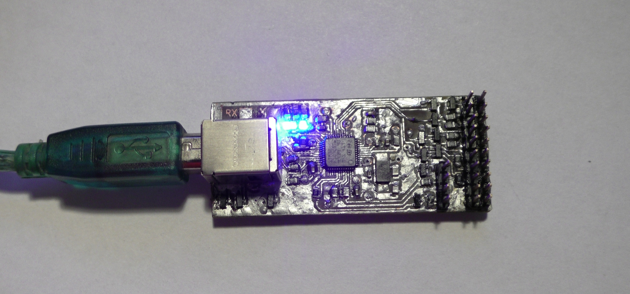
ST-link V2 schematic and PCB in kiCAD with initial firmware through UART
46 parts23

 dltech/stlinkv223
ST-link V2 schematic and PCB in kiCAD with initial firmware through UART
Stlinkv2 is an open-source printed circuit board by dltech, from the dltech/stlinkv2 repository on GitHub. It is a 2-layer board with 60 parts on 53 nets, routed with 603 tracks and 19 vias.
It is built around the BZX84-C5V1. Its parts include 24 resistors, 15 diodes, 13 capacitors, 5 connectors and 2 ICs. It belongs with the STM32 boards of this library.
ST-link V2 schematic and PCB in kiCAD with initial firmware through UART.
On the linux using the Virtualbox software this method is working too.
| Qty | Value | Footprint | References |
|---|---|---|---|
| 12 | BZX84-C5V1 | Diode_SMD:D_SOT-23_ANK | D1, D2, D3, D4, D5, D6, D7, D8, D9, D10, D11, D12 |
| 10 | 75 | Resistor_SMD:R_0805_2012Metric_Pad1.15x1.40mm_HandSolder | R11, R12, R13, R14, R15, R16, R17, R18, R20, R21 |
| 9 | 0.1 | Capacitor_SMD:C_0805_2012Metric_Pad1.15x1.40mm_HandSolder | C2, C3, C6, C8, C9, C10, C11, C12, C13 |
| 6 | 100k | Resistor_SMD:R_0805_2012Metric_Pad1.15x1.40mm_HandSolder | R2, R4, R5, R9, R10, R19 |
| 3 | 100 | Resistor_SMD:R_0805_2012Metric_Pad1.15x1.40mm_HandSolder | R22, R23, R24 |
| 3 | 220 | Resistor_SMD:R_0805_2012Metric_Pad1.15x1.40mm_HandSolder | R6, R7, R8 |
| 2 | 10 | Capacitor_SMD:C_0805_2012Metric_Pad1.15x1.40mm_HandSolder | C1, C7 |
| 2 | 22p | Capacitor_SMD:C_0805_2012Metric_Pad1.15x1.40mm_HandSolder | C4, C5 |
| 2 | red | LED_SMD:LED_0603_1608Metric_Pad1.05x0.95mm_HandSolder | D13, D15 |
| 1 | 10 | Resistor_SMD:R_0805_2012Metric_Pad1.15x1.40mm_HandSolder | R1 |
| 1 | 680 | Resistor_SMD:R_0805_2012Metric_Pad1.15x1.40mm_HandSolder | R3 |
| 1 | 8M | Crystal:Crystal_SMD_5032-2Pin_5.0x3.2mm_HandSoldering | Y1 |
| 1 | AZ1117-3.3 | Package_TO_SOT_SMD:SOT-223-3_TabPin2 | U1 |
| 1 | Conn_01x04 | Connector_Wire:SolderWire-0.25sqmm_1x04_P4.5mm_D0.65mm_OD2mm | J5 |
| 1 | JTAG | micro:PinSocket_2x10_P2.54mm_Vertical | J3 |
| 1 | RX | TestPoint:TestPoint_Pad_3.0x3.0mm | J2 |
| 1 | STM32F103C8Tx | Package_QFP:TQFP-48_7x7mm_P0.5mm | U2 |
| 1 | SWIMM | Connector_PinSocket_2.54mm:PinSocket_1x04_P2.54mm_Vertical | J4 |
| 1 | TX | TestPoint:TestPoint_Pad_3.0x3.0mm | J1 |
| 1 | green | LED_SMD:LED_0603_1608Metric_Pad1.05x0.95mm_HandSolder | D14 |
60 parts, built around the BZX84-C5V1. The full list of its parts is on this page, with links to each part's symbol and footprint where PCBKit's library has them.
From the dltech/stlinkv2 repository on GitHub, at the commit this page was made from: the board is wire/stlinkv2.kicad_pcb. PCBKit opens the board in the browser, with nothing to install.
Its repository states no licence, so its author keeps all rights: ask dltech before reusing the design.
dltech/stlinkv2
ST-link V2 schematic and PCB in kiCAD with initial firmware through UART


sd2psx/pcb
The PCB must be produced in 0.8mm thickness. Production files are provided under the "Releases" tab. These do not include the through-hole OLED module.


