2 layers85 × 56.5 mm

 astuder/ModemHAT56
Classic Phone Modem HAT for the Raspberry Pi
ModemHAT is an open-source printed circuit board by astuder, from the astuder/ModemHAT repository on GitHub. It is a 2-layer board of 85 × 56.5 mm with 111 parts on 110 nets, routed with 764 tracks and 197 vias.
It is built around the 74LVC541AD, LM4819M and SI2457-D-FT, with the SI3018-F-GS, CAT24C32YI-GT3 and 25LC320AT-I/ST among its other parts. Its parts include 41 resistors, 30 capacitors, 9 diodes, 6 ICs and 5 transistors.


This HAT is a modem that connects the Raspberry Pi to a plain old analog telephone line.
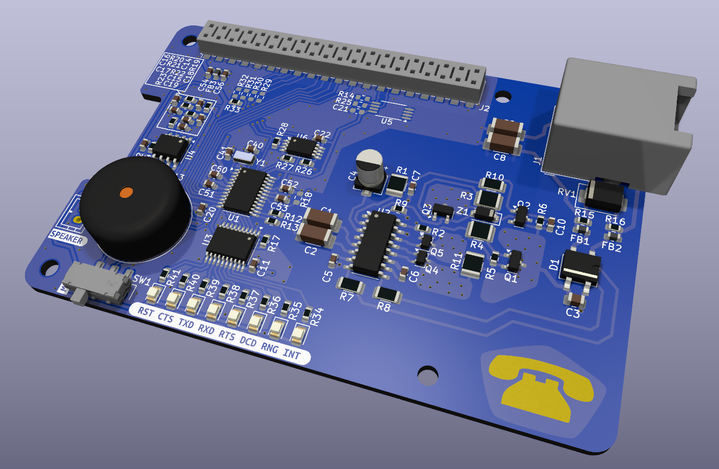
The modem presents itself to the Raspberry Pi on an UART and is controlled with the classic AT command set. It supports various standards (V.22bis, V.32bis, V.34, V.90, ...) at speeds of up to 56 kbps.
The design is based on a Skyworks ISOmodem chipset, specifically Si2457 data modem and Si3018 line side driver. The implementation closely follows the circuits described in application note AN93.
The Modem HAT was successfully tested on the Shadytel phone network at Toorcamp 2022.
[!CAUTION] Whatever your jurisdiction, we're pretty positive that connecting this device to the public phone system IS NOT LEGAL! Don't blame us if you get into trouble.
[!NOTE] This information was tested on Raspberry Pi 4 and Raspberry 5, running Raspberry Pi OS 12 (Bookworm). There may be differences for other versions of the Pi and/or Pi OS.
The modem HAT requires a Raspberry Pi 4 or newer.
The modem communicates through the Pi's UART on GPIO 8-11, and requires CTS and RTS for flow control. The modem supports automatic baudrate detection at speeds up to 307.2 kps.
Before first use after power-up, the modem needs to be reset. To reset the modem, GPIO25 (pin 22) is set low for at least 500ms, then set high, followed by a delay of at least 300ms.
By default, the modem is configured for operation in the United States. For other countries the modem may have to be reconfigured after reset. See AN93 chapter 6.2 for details.
Below are the configuration steps for Raspberry Pi 4 and Raspberry Pi 5.
To enable the UART, edit /boot/firmware/config.txt and add the following line at the end of the file:
dtoverlay=uart4,ctsrts
After rebooting the Raspberry Pi, the UART is mapped to /dev/ttyAMA4.
To reset the modem, run the Python script reset-pi4.py.
The modem is now ready to use. For example connect to the modem by running:
screen /dev/ttyAMA4 115200
Once connected to the modem, if you type at and press enter, the modem should respond with OK.
To enable the UART, edit /boot/firmware/config.txt and add the following line at the end of the file:
dtoverlay=uart3-pi5,ctsrts
After rebooting the Raspberry Pi, the UART is mapped to /dev/ttyAMA3.
To reset the modem, run the Python script reset-pi5.py.
The modem is now ready to use. For example connect to the modem by running:
screen /dev/ttyAMA3 115200
Once connected to the modem, if you type at and press enter, the modem should respond with OK.
The modem supports the basic Hayes command set.
For a complete list of supported AT commands as well as configuration registers refer to AN93 chapters 5.4 through 5.7.
Required connections:
| Pin | Description |
|---|---|
| 1 | 3.3V power for modem chipset |
| 2,4 | 5V power for audio amplifier |
| 6 | GND |
| 19 | UART CTS |
| 21 | UART RX |
| 22 | Modem reset, RPi GPIO25 |
| 23 | UART RTS |
| 24 | UART TX |
Optional connections:
| Pin | Description |
|---|---|
| 13 | Modem interrupt, RPi GPIO27 |
| 15 | Modem boot config EEPROM SDIO, RPi GPIO22 |
| 16 | Modem boot config EEPROM CS, RPi GPIO23 |
| 18 | Modem boot config EEPROM CLK, Rpi GPIO24 |
| 27 | RPi config EEPROM SDA |
| 28 | RPi config EEPROM SCL |
In the standard configuration of the HAT, the modem boot config and interrupt pins are not electrically connected to the Rasbperry Pi GPIO header. Populate R29-R32 with 0-ohm resistors to use these pins.
Large parts of the HAT are based on the hardware design reference in application note AN93 chapter 4. Where applicable, identical component designators are used to simplify cross-referencing.
I used solder paste, stencil and reflow oven for assembly of the HAT. I also ordered partially assembled boards from JLCPCB, and manually soldered the parts that they didn't have in stock (modem chipset and high-voltage capacitors).
After soldering the through-hole parts (RJ11 connector, speaker), make sure to clip the leads on the bottom side of the HAT to avoid shorting with metal parts on the Raspberry Pi.
The modem chipset consists of the digital part Si2457 (U1) and analog part Si3018 (U2).
These are expensive parts, costing US $13-$16 and $6-$8 respectively when purchased from reputable distributors. While tempting, beware of sources like Ebay and AliExpress as parts may be salvaged, old or even fake. It will be much easier to diagnose problems without having to second guess whether the core components of the HAT are genuine.
The HAT uses a 32.768 kHz crystal (Y1) to clock the Si2457, mainly chosen for small size and because I already had a few in my parts bin. The downside of this choice are the slow reset sequence (800 ms) and that this clocking option is only supported by Si2457 revision D (part number SI2457-D-FT) or newer.
If you suspect that you're stuck with an old part, you could try using a 4.9152 MHz crystal instead. In that case you must remove R17 which configures the clock speed. You may also have to replace the load capacitors (C40, C41) with appropriate values. See AN93 chapter 4.1.3 for details.
On the analog side, most of the resistors, capacitors, diodes and transistors have critical voltage, current and/or power ratings. These are all called out in the schematic. See bill of material in AN93 chapter 4.3 for full details.
For bring-up and troubleshooting of the modem portion of the circuit, refer to AN93 chapter 10.1.
The audio output is optional and allows monitoring of connection progress via a speaker, and who doesn't love the old-school sounds of two dial-up modems negotiating a session. It's half the reason to build this project! :)
The audio amplifier LM4819 (U4) can be substituted with the higher power, pin-compatible LM4862. Cheap, off-brand substitutes are probably fine too.
The HAT has a footprint for a 15mm speaker, like for example CUI Devices CVS-1508. Alternatively, footprint J3 provides connectivity via a JST-PH connector, or directly soldering speaker wires to the pads.
If audio is not needed, the audio amplifier (U4) and associated parts (C12-C19, R19-R24, SW1, J3) can be left unpopulated.
To enable audio output on the speaker, make sure MUTE switch is set towards the LEDs. The AT command to enable speaker output while dialing and handshaking is ATM1. Speaker volume is controlled with ATL1 through ATL4, where 4 is the loudest.
The modem boot config EEPROM is optional and can store AT commands that the modem automatically runs after reset. See AN93 chapter 2.7 for details.
The EEPROM can be programmed by the modem with AT commands. For hacking, the EEPROM can also be connected to the Raspberry Pi by populating R29, R30 and R31. For the latter, keep the modem in reset while interacting with the EEPROM.
If this functionality is not needed, the EEPROM (U6) and associated parts (C22, R26, R27, R28) can be left unpopulated.
The HAT ID EEPROM is optional and can store information that allows the Raspberry Pi to recognize the HAT and load the required device tree overlay, i.e. automatically configure UART and other pins.
I haven't figured out the content for this EEPROM yet. Specification is here. Contributions are welcome :)
If this functionality is not needed, the EEPROM (U5) and associated parts (C21, R14, R25) can be left unpopulated.
| Qty | Value | Footprint | References |
|---|---|---|---|
| 14 | 0.1uF | Capacitor_SMD:C_0603_1608Metric | C5, C6, C11, C14, C15, C16, C17, C18, C20, C21, C22, C50, C52, C56 |
| 11 | 1K | Resistor_SMD:R_0603_1608Metric | R20, R21, R22, R34, R35, R36, R37, R38, R39, R40, R41 |
| 8 | GRN | LED_SMD:LED_0805_2012Metric | D2, D3, D4, D5, D6, D7, D8, D9 |
| 7 | 10K | Resistor_SMD:R_0603_1608Metric | R17, R18, R19, R23, R27, R28, R33 |
| 6 | 0R | Resistor_SMD:R_0603_1608Metric | R15, R16, R29, R30, R31, R32 |
| 4 | M2.5 | MountingHole:MountingHole_2.7mm_M2.5 | H1, H2, H3, H4 |
| 3 | 1uF | Capacitor_SMD:C_0603_1608Metric | C13, C19, C54 |
| 3 | 600R @100M | Inductor_SMD:L_0603_1608Metric | FB1, FB2, FB3 |
| 2 | 0.22uF | Capacitor_SMD:C_0603_1608Metric | C51, C53 |
| 2 | 100K | Resistor_SMD:R_0603_1608Metric | R5, R6 |
| 2 | 150R | Resistor_SMD:R_0603_1608Metric | R2, R26 |
| 2 | 18pF | Capacitor_SMD:C_0603_1608Metric | C40, C41 |
| 2 | 20M | Resistor_SMD:R_1206_3216Metric | R7, R8 |
| 2 | 3.9K | Resistor_SMD:R_0603_1608Metric | R14, R25 |
| 2 | 33pF Y2 | ModemHAT:C_1808_4520Metric | C1, C2 |
| 2 | 56R | Resistor_SMD:R_0603_1608Metric | R12, R13 |
| 2 | 680pF Y2 | ModemHAT:C_1808_4520Metric | C8, C9 |
| 2 | NPN 300V 0.5A | Package_TO_SOT_SMD:SOT-23 | Q1, Q3 |
| 2 | NPN 80V 330mW | Package_TO_SOT_SMD:SOT-323_SC-70 | Q4, Q5 |
| 1 | 0.01uF | Capacitor_SMD:C_0603_1608Metric | C10 |
| 1 | 0.01uF 250V | Capacitor_SMD:C_0805_2012Metric | C3 |
| 1 | 1.07K 1/2W | Resistor_SMD:R_1210_3225Metric | R1 |
| 1 | 1M | Resistor_SMD:R_0603_1608Metric | R9 |
| 1 | 1uF 50V | Capacitor_SMD:CP_Elec_4x5.4 | C4 |
| 1 | 2.49K 1/2W | Resistor_SMD:R_1210_3225Metric | R4 |
| 1 | 2.7nF 50V | Capacitor_SMD:C_0603_1608Metric | C7 |
| 1 | 24LC32 | Package_SO:TSSOP-8_4.4x3mm_P0.65mm | U5 |
| 1 | 25LC320 | Package_SO:TSSOP-8_4.4x3mm_P0.65mm | U6 |
| 1 | 2x20 0.1" Stacking Header | ModemHAT:Raspberry_Pi_Stacking_Header | J2 |
| 1 | 3.65K 1/2W | Resistor_SMD:R_1210_3225Metric | R3 |
| 1 | 300V 225mA | ModemHAT:TO-269AA-R | D1 |
| 1 | 32.768kHz 25ppm | Crystal:Crystal_SMD_3215-2Pin_3.2x1.5mm | Y1 |
| 1 | 43V 1/2W | Diode_SMD:D_SOD-123 | Z1 |
| 1 | 47K | Resistor_SMD:R_0603_1608Metric | R24 |
| 1 | 47pF | Capacitor_SMD:C_0603_1608Metric | C12 |
| 1 | 536R 1/4W | Resistor_SMD:R_1206_3216Metric | R10 |
| 1 | 73.2R 1/2W | Resistor_SMD:R_1210_3225Metric | R11 |
| 1 | 74LVC541 | Package_SO:TSSOP-20_4.4x6.5mm_P0.65mm | U3 |
| 1 | G*** | kibuzzard-62720846 | kibuzzard-62720846 |
| 1 | G*** | kibuzzard-665D1212 | kibuzzard-665D1212 |
| 1 | G*** | kibuzzard-665D11B2 | kibuzzard-665D11B2 |
| 1 | JST | Connector_JST:JST_PH_B2B-PH-K_1x02_P2.00mm_Vertical | J3 |
| 1 | LM4819 | Package_SO:SOIC-8_3.9x4.9mm_P1.27mm | U4 |
| 1 | LOGO | ModemHAT:model-text2 | G*** |
| 1 | LOGO | ModemHAT:shodytel-text-small | G*** |
| 1 | P3100SB | Diode_SMD:D_SMB | RV1 |
| 1 | PNP 300V 0.5A | Package_TO_SOT_SMD:SOT-23 | Q2 |
| 1 | RJ11 | Connector_RJ:RJ12_Amphenol_54601-x06_Horizontal | J1 |
| 1 | SW_SPDT | Button_Switch_SMD:SW_SPDT_CK_JS102011SAQN | SW1 |
| 1 | Si2457 | Package_SO:TSSOP-24_4.4x7.8mm_P0.65mm | U1 |
| 1 | Si3018 | Package_SO:SOIC-16_3.9x9.9mm_P1.27mm | U2 |
| 1 | Speaker | Buzzer_Beeper:Buzzer_15x7.5RM7.6 | LS1 |
It measures 85 × 56.5 mm and has 2 copper layers, 1.6 mm thick.
111 parts, built around the 74LVC541AD, LM4819M, SI2457-D-FT and SI3018-F-GS. The full list of its parts is on this page, with links to each part's symbol and footprint where PCBKit's library has them.
From the astuder/ModemHAT repository on GitHub, at the commit this page was made from: the board is ModemHAT.kicad_pcb and its schematic ModemHAT.kicad_sch. PCBKit opens the board in the browser, with nothing to install.
Its repository states no licence, so its author keeps all rights: ask astuder before reusing the design.


CPTforever/8088-MicroATX-Computer
A 8088 based, IBM 5150 like computer compatible with the MicroATX motherboard form factor.

LimesOrLemons/Macropaduno
An ESP32-S3 handheld controller with a custom PCB and 3D-printed enclosure for numerous programmable functions.


Neumi/ethersweep
Open Source, easy to use Ethernet connected stepper motor controller. Built in FreeCAD, KiCAD and Arduino.

OLIMEX/ESP32-GATEWAY
ESP32 IoT Gateway board with BLE WIFI and Ethernet