2 layers54 × 94 mm
 ScotteC/timer-display
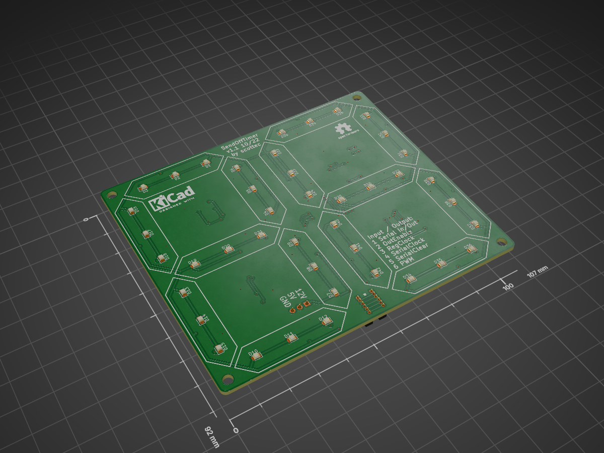
Timer display is an open-source printed circuit board by ScotteC, from the ScotteC/timer-display repository on GitHub. It is a 2-layer board of 107 × 92 mm with 149 parts on 141 nets, routed with 893 tracks and 98 vias.
It is built around the SN74LS08D, LTST-C171KRKT and MBT3904DW1, with the T2N7002AK,LM among its other parts. Its parts include 56 resistors, 42 diodes, 28 transistors, 6 capacitors and 6 ICs. It belongs with the lEDs and displays boards of this library.


| Qty | Value | Footprint | References |
|---|---|---|---|
| 42 | LTST-C171KRKT | LED_SMD:LED_0805_2012Metric | D1, D2, D10, D11, D12, D13, D14, D15, D16, D17, D18, D19, D20, D21, D22, D23 +26 |
| 14 | 100k | Resistor_SMD:R_0603_1608Metric | R43, R44, R45, R46, R47, R48, R49, R50, R51, R52, R53, R54, R55, R56 |
| 14 | 10k | Resistor_SMD:R_0603_1608Metric | R1, R4, R7, R10, R13, R16, R19, R22, R25, R28, R31, R34, R37, R40 |
| 14 | 1k | Resistor_SMD:R_0603_1608Metric | R2, R5, R8, R11, R14, R17, R20, R23, R26, R29, R32, R35, R38, R41 |
| 14 | 36 | Resistor_SMD:R_0603_1608Metric | R3, R6, R9, R12, R15, R18, R21, R24, R27, R30, R33, R36, R39, R42 |
| 14 | MBT3904DW1 | Package_TO_SOT_SMD:SOT-363_SC-70-6 | Q1, Q3, Q5, Q7, Q9, Q11, Q13, Q15, Q17, Q19, Q21, Q23, Q25, Q27 |
| 14 | T2N7002AK,LM | Package_TO_SOT_SMD:SOT-23 | Q2, Q4, Q6, Q8, Q10, Q12, Q14, Q16, Q18, Q20, Q22, Q24, Q26, Q28 |
| 6 | 100n | Capacitor_SMD:C_0603_1608Metric | C1, C2, C3, C4, C5, C6 |
| 4 | MountingHole | MountingHole:MountingHole_3.2mm_M3 | H1, H2, H3, H4 |
| 4 | SN74LS08 | Package_SO:SOIC-14_3.9x8.7mm_P1.27mm | U1, U3, U4, U6 |
| 2 | SN74HC595DT | Package_SO:SOIC-16_3.9x9.9mm_P1.27mm | U2, U5 |
| 1 | IN | Connector_PinSocket_1.27mm:PinSocket_1x06_P1.27mm_Vertical | J2 |
| 1 | OUT | Connector_PinSocket_1.27mm:PinSocket_1x06_P1.27mm_Vertical | J3 |
| 1 | PWR | Connector_PinSocket_2.54mm:PinSocket_1x03_P2.54mm_Vertical | J1 |
The 145 most common of 149 parts.
It measures 107 × 92 mm and has 2 copper layers, 1.6 mm thick.
149 parts, built around the SN74LS08D, LTST-C171KRKT, MBT3904DW1 and T2N7002AK,LM. The full list of its parts is on this page, with links to each part's symbol and footprint where PCBKit's library has them.
From the ScotteC/timer-display repository on GitHub, at the commit this page was made from: the board is timer-display.kicad_pcb and its schematic segment.kicad_sch. PCBKit opens the board in the browser, with nothing to install.
Its repository states no licence, so its author keeps all rights: ask ScotteC before reusing the design.

oresat/oresat-gps-hardware
Hardware for OreSat's SDR GPS receive and other SDR GPS projects


PubInv/krake
The Krake™ is a Wi-Fi–enabled server using an MQTT broker, which means it can be controlled remotely by other devices ("clients") via the internet.

PubInv/general-purpose-alarm-device
A general purpose alarm device (with software) as a module for medical devices (and others)


PCB-Design-MIT/Wi-Fi-Controlled-RGB-Light
A demo board for students to learn to solder and debug


ShawnHymel/esp8266-temp-proto
This is a quick prototype designed for the Bantam Tools Desktop PCB Milling Machine. It uses an ESP8266-WROOM-02 module connected to an MCP9808 temperature sensor.