4 layers19 × 34 mm
NRF24PA
bemelab/nrf24L01-modules
nRF24L01+ tabanlı RF modül tasarımları. Her proje kendi klasöründe, kendi README'si ve tasarım notlarıyla durur.
39 parts
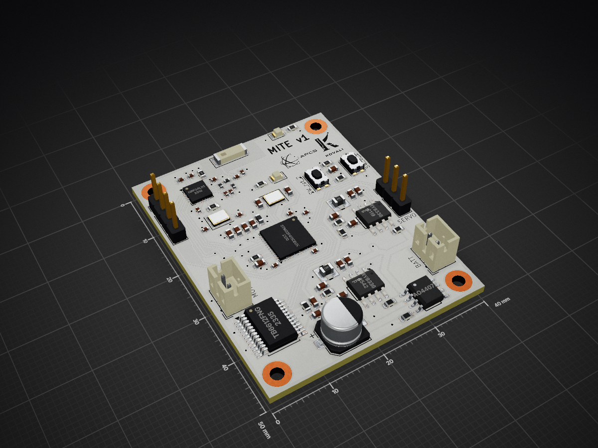
 SySch415/MITE-ESC5
Electronic Speed Controller for SCX24 rock crawlers
Crawler schematic is an open-source printed circuit board by SySch415, from the SySch415/MITE-ESC repository on GitHub, published under the MIT licence. It is a 4-layer board of 40 × 50 mm with 82 parts on 80 nets, routed with 528 tracks and 69 vias.
It is built around the STM32F411CEU6, NRF24L01P-R and TB6612FNG,C,8,EL, with the RY8336, RC0603FR-0710KL and FTC303018D4R7MBCA among its other parts. Its parts include 5 ICs, 3 connectors, 2 resistors, 2 inductors and 1 transistor. It belongs with the STM32 boards of this library.


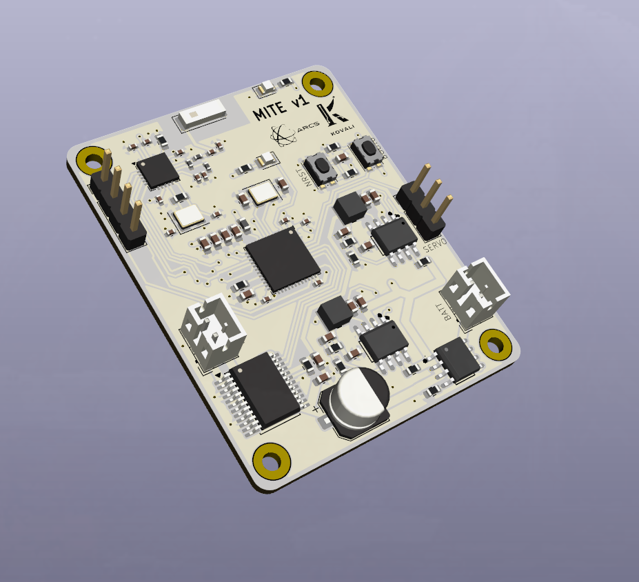
A from-scratch Electronic Speed Controller for SCX24 rock crawlers, built around the STM32F411. It has two parts:
Both firmwares are bare-metal C++17: no vendor HAL and no CubeMX-generated code. They're built on a register-level HAL (STM32-HAL-Library, included as a submodule) and a custom nRF24L01+ driver.
Status
- Crawler and controller firmware run on prototype (two Black Pill boards).
- MITE v1 (custom crawler PCB): layout about 90% done, antenna needs impedance matching, then going through CDR, not yet fabricated. The firmware pin map has to be updated for the new board (see Pin maps).
- Controller PCB: schematic captured, layout not started.
.
├── controller/            # Transmitter firmware (joystick → nRF24 TX)
│   ├── main.cpp
│   └── startup.cpp        # Vector table + Reset_Handler
├── crawler/               # Receiver firmware (nRF24 RX → motor + servo)
│   ├── main.cpp
│   └── startup.cpp
├── drivers/
│   ├── include/nrf24.hpp  # nRF24L01+ driver
│   └── src/nrf24.cpp
├── hal_lib/               # Submodule: SySch415/STM32-HAL-Library (GPIO, RCC, SPI, ADC, TIM)
├── hardware/
│   ├── crawler_schematic/     # KiCad project: MITE v1 crawler board
│   ├── controller_schematic/  # KiCad project: controller
│   └── original-schematic-STM32F411CEU6_WeAct_Black_Pill_V2.0.pdf  # reference
├── docs/images/           # README images
├── linker.ld              # STM32F411CE: 512 KB flash, 128 KB SRAM
└── CMakeLists.txt # Builds controller.elf and crawler.elfarm-none-eabi-gcc toolchainThe HAL is a git submodule, so clone recursively:
git clone --recursive https://github.com/SySch415/stm32-crawler.git
# or, in an existing clone:
git submodule update --initcmake -B build
cmake --build buildThis produces controller.elf/.bin and crawler.elf/.bin in build/.
With the ST-Link connected to the target's SWD pins:
cmake --build build --target flash-crawler
cmake --build build --target flash-controller
Each target erases, writes to 0x08000000, verifies, and resets the MCU through OpenOCD.
The controller transmits continuously, and the crawler listens on pipe 0.
| Setting | Value |
|---|---|
| RF channel | 76 (2.476 GHz) |
| Address | E7:E7:E7:E7:E7 (5 bytes) |
| Data rate / power | 2 Mbps, 0 dBm |
| CRC | 1 byte |
| Auto-ack / retransmit | Disabled |
| Payload | 4 bytes, fixed length |
Payload format (little-endian):
| Bytes | Field | Range |
|---|---|---|
| 0–1 | Throttle (uint16_t) | 0–4095 (12-bit ADC), center ≈ 2048 |
| 2–3 | Steering (uint16_t) | 0–4095 (12-bit ADC), center ≈ 2048 |
Throttle → TB6612FNG channel A
Steering → servo
Status LEDs (prototype firmware): throttle forward/reverse and steering left/right indicators.
Crawler
| Signal | Pin | Peripheral |
|---|---|---|
| nRF CE | PA3 | GPIO |
| nRF CSN | PA4 | GPIO |
| nRF SCK | PA5 | SPI1 (AF5) |
| nRF MISO | PA6 | SPI1 (AF5) |
| nRF MOSI | PA7 | SPI1 (AF5) |
| Motor PWM (PWMA) | PB6 | TIM4_CH1 (AF2) |
| AIN1 | PB7 | GPIO |
| AIN2 | PB8 | GPIO |
| Servo PWM | PB4 | TIM3_CH1 (AF2) |
| LED throttle up / down | PA0 / PA1 | GPIO |
| LED steering left / right | PA11 / PA12 | GPIO |
Controller
| Signal | Pin | Peripheral |
|---|---|---|
| Joystick Y (throttle) | PA0 | ADC1_IN0 |
| Joystick X (steering) | PA1 | ADC1_IN1 |
| nRF CE / CSN | PA3 / PA4 | GPIO |
| nRF SCK / MISO / MOSI | PA5 / PA6 / PA7 | SPI1 (AF5) |
Several pins moved during PCB layout. The crawler firmware has to be updated before it runs on MITE v1.
| Signal | Pin | Peripheral | Changed? |
|---|---|---|---|
| nRF CE | PA3 | GPIO | ✱ |
| nRF CSN | PA4 | GPIO | ✱ |
| nRF SCK | PA5 | SPI1_SCK | |
| nRF MISO | PA6 | SPI1_MISO | ✱ |
| nRF MOSI | PA7 | SPI1_MOSI | ✱ |
| nRF IRQ | not connected | (polled over SPI) | |
| Motor PWM (PWMA) | PB4 | TIM3_CH1 | ✱ |
| AIN1 | PB6 | GPIO | ✱ |
| AIN2 | PB5 | GPIO | ✱ |
| Servo PWM | PB7 | TIM4_CH2 | ✱ |
| Status LED | PC13 | GPIO (active low) | ✱ |
| SWDIO / SWCLK | PA13 / PA14 | SWD |
A 40 × 50 mm, 4-layer board that replaces the prototype's Black Pill, nRF module, H-bridge breakout and regulators. The KiCad project is in hardware/crawler_schematic/.
| Block | Part | Notes |
|---|---|---|
| MCU | STM32F411CEU6 (UFQFPN48) | 25 MHz HSE crystal, BOOT0 and reset buttons |
| Radio | nRF24L01+ (bare QFN-20) | 16 MHz crystal, Johanson 2450AT43F0100 chip antenna, Nordic reference matching network |
| Motor driver | TB6612FNG (SSOP-24) | Channel A only; VM from battery |
| Reverse polarity protection | AO4407A P-channel MOSFET | High-side, gate to GND through 10 kΩ |
| Servo rail | RY8336 synchronous buck → 5 V | 4.7 µH molded inductor |
| Logic / RF rail | RY8336 synchronous buck → 3.3 V | 4.7 µH molded inductor |
| Motor bulk capacitor | 47 µF aluminum electrolytic | At the H-bridge VM pins |
| Battery | 2S LiPo (7.4 V nominal, 8.4 V full) | JST-PH |
| Connectors | JST-PH battery, JST-PH motor, 1×3 servo, 1×4 SWD |
flowchart LR
    BAT[2S LiPo] --> FET[AO4407A<br/>reverse polarity]
    FET --> BULK[47 µF bulk cap<br/>star point]
    BULK --> HB[TB6612FNG VM] --> MOT[050 motor]
    BULK --> B5[RY8336 → 5 V] --> SERVO[Steering servo]
    BULK --> B3[RY8336 → 3.3 V]
    B3 --> MCU[STM32F411]
    B3 --> RF[nRF24L01+]
Why it's arranged this way:
JLCPCB JLC04161H-3313, 1.6 mm, impedance controlled.
| Layer | Use |
|---|---|
| L1 (F.Cu) | Components, signals, motor current |
| L2 (In1.Cu) | Solid GND plane, no routing |
| L3 (In2.Cu) | 3.3 V pour |
| L4 (B.Cu) | Signals |
| Item | Value |
|---|---|
| Default track / clearance | 0.2 mm / 0.2 mm |
| Motor nets (BAT_IN, +BATT, AO1, AO2) | 2.0 mm (sized for ~5 A stall) |
| Power nets (+3.3V, +5V) | 0.5 mm, necked down at fine-pitch pins |
| RF feed (50 Ω, grounded coplanar) | 0.40 mm width, 0.25 mm gap |
| Vias | 0.6 mm pad / 0.3 mm drill |
| Copper to board edge | 0.5 mm |
| Pin | Signal |
|---|---|
| 1 | +3.3 V |
| 2 | SWDIO (PA13) |
| 3 | SWCLK (PA14) |
| 4 | GND |
Currently a prototype-level build. The KiCad schematic is in hardware/controller_schematic/, and the PCB isn't laid out yet.
| Part | Notes |
|---|---|
| DFRobot Black Pill (STM32F411) | MCU board |
| nRF24L01+ module | SPI1 |
| 2-axis analog joystick | Throttle (Y) and steering (X) |
| 18650 Li-ion cell | Power |
| MT3608 boost module | 5 V for the Black Pill |
openocd -f interface/stlink.cfg -f target/stm32f4x.cfg).Firmware (controller/, crawler/, drivers/): MIT © 2026 Simon Schmidt
Hardware design files (hardware/): CERN-OHL-P v2 © 2026 Simon Schmidt
The Kovali name and logo are trademarks of Kovali, a California limited liability company. All rights reserved.
The ARCS name and logo belong to Avionics, Robotics, and Control Systems, a nonprofit corporation and IRS-recognized 501(c)(3) public charity, and are used with permission.
If you build, modify, or distribute this board, please remove both logos from the silkscreen. The logo footprints are excluded from the CERN-OHL license.
| Qty | Value | Footprint | References |
|---|---|---|---|
| 6 | DNP | Capacitor_SMD:C_0603_1608Metric | C_ref_1, C_ref_2, C_ref_3, C_ref_4, CFF_3.3, CFF_5 |
| 5 | 10 kOhm | Resistor_SMD:R_0603_1608Metric | R_EN_3.3, R_EN_5, R1_5, R2_3.3, R3_5 |
| 5 | TestPoint | TestPoint:TestPoint_Pad_D1.5mm | TP1, TP2, TP3, TP4, TP5 |
| 3 | 100 nF, X7R, 16 V | Capacitor_SMD:C_0402_1005Metric | C_M_4, C_M_5, C_M_6 |
| 3 | 100nF | Capacitor_SMD:C_0603_1608Metric | C_rst_1, C1_3.3, C1_5 |
| 2 | 10K | Resistor_SMD:R_0603_1608Metric | R_B_1, R_B_2 |
| 2 | 10nF | Capacitor_SMD:C_0402_1005Metric | C_nrf_1, C_nrf_11 |
| 2 | 10uF | Capacitor_SMD:C_0603_1608Metric | C_H_1, C_H_2 |
| 2 | 22pF | Capacitor_SMD:C_0402_1005Metric | C_nrf_8, C_nrf_9 |
| 2 | 22uF | Capacitor_SMD:C_0603_1608Metric | CIN_3.3, CIN_5 |
| 2 | 22x2uF | Capacitor_SMD:C_0603_1608Metric | COUT_3.3, COUT_5 |
| 2 | 4.3pF | Capacitor_SMD:C_0603_1608Metric | C_M_1, C_M_2 |
| 2 | 4.7uH | easyeda2kicad:IND-SMD_L3.0-W3.0_FTC303020D | L1_3.3, L1_5 |
| 2 | Crystal_4pin_GND24 | Crystal:Crystal_SMD_3225-4Pin_3.2x2.5mm | Y_M_1, Y_nrf_1 |
| 2 | JST-PH | Connector_JST:JST_PH_B2B-PH-K_1x02_P2.00mm_Vertical | J1, J2 |
| 2 | RY8336 | easyeda2kicad:ESOP-8_L4.9-W3.9-P1.27-LS6.0-BL-EP-1 | U2, U3 |
| 1 | 1.0pF | Capacitor_SMD:C_0402_1005Metric | C_nrf_4 |
| 1 | 1.5pF | Capacitor_SMD:C_0402_1005Metric | C_nrf_5 |
| 1 | 100 nF, X7R | Capacitor_SMD:C_0402_1005Metric | C_M_7 |
| 1 | 10k Ohm | Resistor_SMD:R_0603_1608Metric | R_H_1 |
| 1 | 10uH +-10% | Inductor_SMD:L_0603_1608Metric | L_M_1 |
| 1 | 1K | Resistor_SMD:R_0603_1608Metric | R_L_1 |
| 1 | 1M | Resistor_SMD:R_0603_1608Metric | R_nrf_2 |
| 1 | 1nF | Capacitor_SMD:C_0402_1005Metric | C_nrf_2 |
| 1 | 2.2nF | Capacitor_SMD:C_0402_1005Metric | C_nrf_7 |
| 1 | 2.2uF | Capacitor_SMD:C_0603_1608Metric | C_M_3 |
| 1 | 2.7nH | Inductor_SMD:L_0402_1005Metric | L_nrf_3 |
| 1 | 22k | Resistor_SMD:R_0603_1608Metric | R_nrf_1 |
| 1 | 25.68 kOhm | Resistor_SMD:R_0603_1608Metric | R1_3.3 |
| 1 | 3.9nH | Inductor_SMD:L_0402_1005Metric | L_nrf_2 |
| 1 | 33nF | Capacitor_SMD:C_0402_1005Metric | C_nrf_3 |
| 1 | 4.7pF | Capacitor_SMD:C_0402_1005Metric | C_nrf_6 |
| 1 | 44.05 kOhm | Resistor_SMD:R_0603_1608Metric | R2_5 |
| 1 | 47uF | Capacitor_SMD:CP_Elec_6.3x5.4 | C_H_3 |
| 1 | 5.1K | Resistor_SMD:R_0603_1608Metric | R_L_2 |
| 1 | 50ohm | RF_Antenna:Johanson_2450AT43F0100 | AE1 |
| 1 | 8.2nH | Inductor_SMD:L_0402_1005Metric | L_nrf_1 |
| 1 | AO4407A | easyeda2kicad:SOIC-8_L4.9-W3.9-P1.27-LS6.0-BL | Q1 |
| 1 | LED_pc13 | LED_SMD:LED_0805_2012Metric | D_L_1 |
| 1 | LED_pwr | LED_SMD:LED_0805_2012Metric | D_L_2 |
| 1 | LOGO | footprints:arcs_8mm_logo | G*** |
| 1 | LOGO | footprints:kovali_9mm | G*** |
| 1 | Motor_Servo | Connector_PinHeader_2.54mm:PinHeader_1x03_P2.54mm_Vertical | M2 |
| 1 | NC | Resistor_SMD:R_0603_1608Metric | R_rst_1 |
| 1 | NRF24L01 | Package_DFN_QFN:QFN-20-1EP_4x4mm_P0.5mm_EP2.5x2.5mm | U6 |
| 1 | STM32F411CEUx | Package_DFN_QFN:QFN-48-1EP_7x7mm_P0.5mm_EP5.6x5.6mm | U1 |
| 1 | SWD_Header | Connector_PinHeader_2.54mm:PinHeader_1x04_P2.54mm_Vertical | J3 |
| 1 | TB6612FNG | Package_SO:SSOP-24_5.3x8.2mm_P0.65mm | U4 |
| 1 | boot switch | Button_Switch_SMD:SW_Push_1P1T_NO_CK_KMR2 | SW_B_1 |
| 1 | nrst_switch | Button_Switch_SMD:SW_Push_1P1T_NO_CK_KMR2 | SW_rst_2 |
The 78 most common of 82 parts.
It measures 40 × 50 mm and has 4 copper layers, 1.57 mm thick.
82 parts, built around the STM32F411CEU6, NRF24L01P-R, TB6612FNG,C,8,EL and RY8336. The full list of its parts is on this page, with links to each part's symbol and footprint where PCBKit's library has them.
From the SySch415/MITE-ESC repository on GitHub, at the commit this page was made from: the board is hardware/crawler_schematic/crawler_schematic.kicad_pcb and its schematic hardware/controller_schematic/controller_schematic/controller_schematic.kicad_sch. PCBKit opens the board in the browser, with nothing to install.
Its repository publishes it under the MIT licence: you may reuse it on that licence's terms (keep the author's notice, and for a copyleft licence share your changes alike).
bemelab/nrf24L01-modules
nRF24L01+ tabanlı RF modül tasarımları. Her proje kendi klasöründe, kendi README'si ve tasarım notlarıyla durur.


xmyoot/custom-round-pcb-led-flash
Custom circular ring PCB LED flash controller prototype


aditelik/bldc_controller
Brushless DC Motor Controller PCB Design for EE 91a Fall 2019

