2 layers68 × 110 mm

 schuyler4/Multimeter3
My multimeter design.
Multimeter is an open-source printed circuit board by schuyler4, from the schuyler4/Multimeter repository on GitHub, published under the MIT licence. It is a 2-layer board of 68 × 110 mm with 99 parts on 118 nets, routed with 934 tracks and 172 vias.
It is built around the SC0915, MCP3561-E/NC and CC56-12SURKWA, with the OPA4388IDR-TP, BSS84 and LTST-C170KRKT among its other parts. Its parts include 50 resistors, 24 transistors, 5 ICs, 4 diodes and 3 capacitors. It belongs with the sensors and measurement boards of this library.


This is my homebrew multimeter. It differs from standard multimeters in several respects.
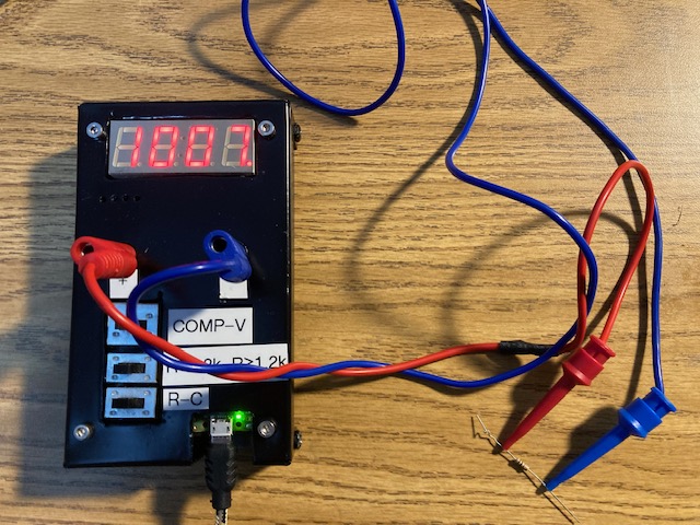
Calibration is relative to my Fluke 101 Multimeter. I know that there is probably some technical problems with this, as the Fluke 101 does not have more digits than this meter, nor is it substantially more accurate in voltage mode. However, I don't have a really nice bench top meter, so it will have to do.
| Qty | Value | Footprint | References |
|---|---|---|---|
| 16 | 1k | Resistor_SMD:R_0805_2012Metric_Pad1.20x1.40mm_HandSolder | R9, R10, R11, R12, R32, R33, R34, R35, R45, R46, R47, R48, R49, R50, R51, R52 |
| 16 | 2N7002 | Package_TO_SOT_SMD:SOT-23 | Q1, Q2, Q3, Q4, Q12, Q14, Q15, Q16, Q17, Q18, Q19, Q20, Q21, Q22, Q23, Q24 |
| 14 | 649 | Resistor_SMD:R_0805_2012Metric_Pad1.20x1.40mm_HandSolder | R5, R13, R14, R15, R16, R17, R18, R19, R20, R28, R29, R30, R31, R38 |
| 13 | 10k | Resistor_SMD:R_0805_2012Metric_Pad1.20x1.40mm_HandSolder | R1, R2, R4, R6, R22, R23, R24, R25, R26, R27, R42, R43, R44 |
| 8 | BSS84 | Package_TO_SOT_SMD:SOT-23 | Q5, Q6, Q7, Q8, Q9, Q10, Q11, Q13 |
| 4 | LTST-C170KRKT | LED_SMD:LED_0805_2012Metric | D1, D2, D3, D4 |
| 4 | M3 | MountingHole:MountingHole_2.7mm_Pad_Via | H1, H2, H3, H4 |
| 3 | 0.1uF | Capacitor_SMD:C_0805_2012Metric | C4, C5, C6 |
| 3 | 10k+/-0.1% | Resistor_SMD:R_0805_2012Metric_Pad1.20x1.40mm_HandSolder | R39, R40, R41 |
| 3 | Pad | TestPoint:TestPoint_THTPad_1.5x1.5mm_Drill0.7mm | TP1, TP2, TP3 |
| 1 | 1.62k | Resistor_SMD:R_0805_2012Metric_Pad1.20x1.40mm_HandSolder | R36 |
| 1 | 100k+/-0.1% | Resistor_SMD:R_0805_2012Metric_Pad1.20x1.40mm_HandSolder | R21 |
| 1 | 10k | Capacitor_SMD:C_0805_2012Metric_Pad1.18x1.45mm_HandSolder | R3 |
| 1 | 4952 | Connector_Pin:Pin_D1.2mm_L10.2mm_W2.9mm_FlatFork | TP4 |
| 1 | 511k+/-0.1% | Resistor_SMD:R_0805_2012Metric_Pad1.20x1.40mm_HandSolder | R37 |
| 1 | Black Banana Plug | Multimeter:KEYSTONE_575-4 | J4 |
| 1 | CC56-12SURKWA | Display_7Segment:CA56-12SURKWA | U4 |
| 1 | GF-123-0054 | Multimeter:SW_GF-123-0054 | SW1 |
| 1 | GF-126-0159 | Multimeter:SW_GF-126-0159 | SW2 |
| 1 | GF-161-0005 | Multimeter:GF-161-0005 | SW3 |
| 1 | LM4030-2.5 | Package_TO_SOT_SMD:SOT-23-5 | U7 |
| 1 | MCP3561 | Package_SO:SSOP-20_4.4x6.5mm_P0.65mm | U10 |
| 1 | OPA4388IDR | Package_SO:SOIC-14_3.9x8.7mm_P1.27mm | U3 |
| 1 | Red Banana Plug | Multimeter:KEYSTONE_575-4 | J3 |
| 1 | SC0915 | Multimeter:MODULE_SC0915 | U1 |
It measures 68 × 110 mm and has 2 copper layers, 1.6 mm thick.
99 parts, built around the SC0915, MCP3561-E/NC, CC56-12SURKWA and OPA4388IDR-TP. The full list of its parts is on this page, with links to each part's symbol and footprint where PCBKit's library has them.
From the schuyler4/Multimeter repository on GitHub, at the commit this page was made from: the board is electronics/rev2/ecad/Multimeter.kicad_pcb and its schematic electronics/rev1/ecad/Multimeter.kicad_sch. PCBKit opens the board in the browser, with nothing to install.
Its repository publishes it under the MIT licence: you may reuse it on that licence's terms (keep the author's notice, and for a copyleft licence share your changes alike).


Spadeyache/FATEN-RCJ26
Key features we have. PostTrainingQuantization(PTQ) with results simulated on the K230D chip, half-duplex serial driver with 74HCT126, asymmetric PID dependent on the IMU, custom touch sensors, and an IR camera used on…


KLFAMO/relock_Artiq
This project is an electronic device based on the STM32 microcontroller, equipped with an Ethernet port for remote control and data communication.

UoM-Robotics-Society/ROV-project
Software, mechanical design and hardware for ROV

DPIclimate/ag-node
Automatic multi-weigh-station for measuring the live-weight of sheep in remote locations.

umass-ece-sdp/sdp26-1
Autonomous DJI Tello target-tracking platform with a wearable glove controller. A Jetson host (or Linux laptop) runs vision and flight control while an ESP32-S3 glove sends discrete range commands over Wi-Fi.