2 layers68 × 110 mm

 edmundsj/MCP3561DevBoard6
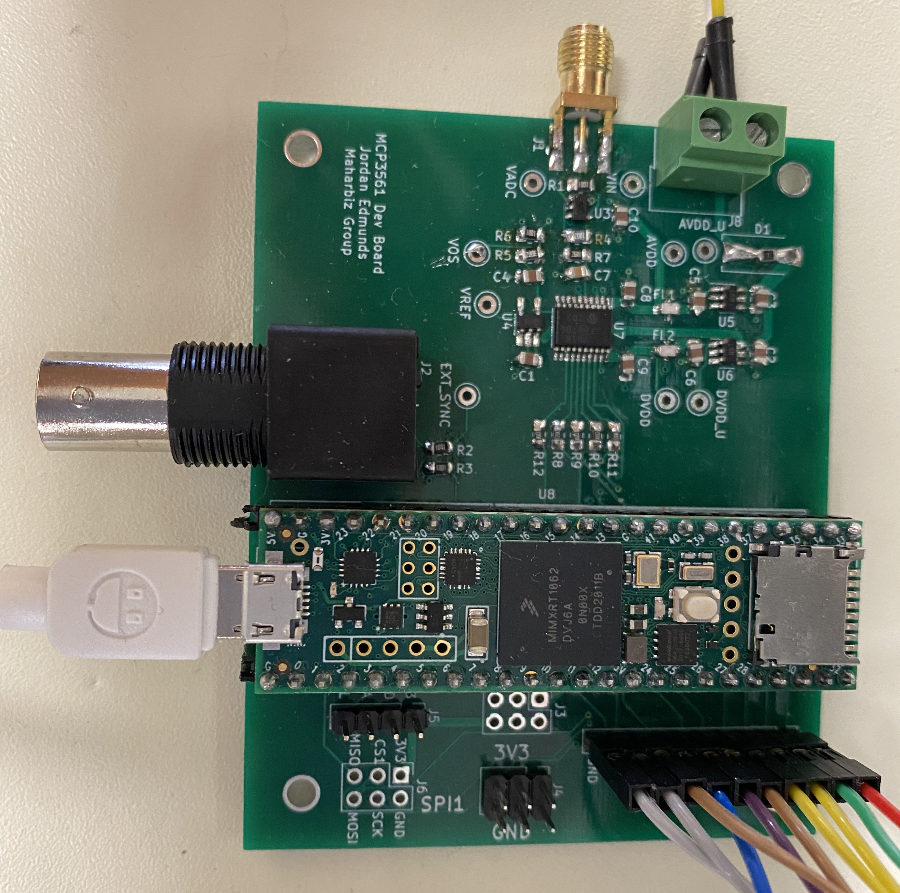
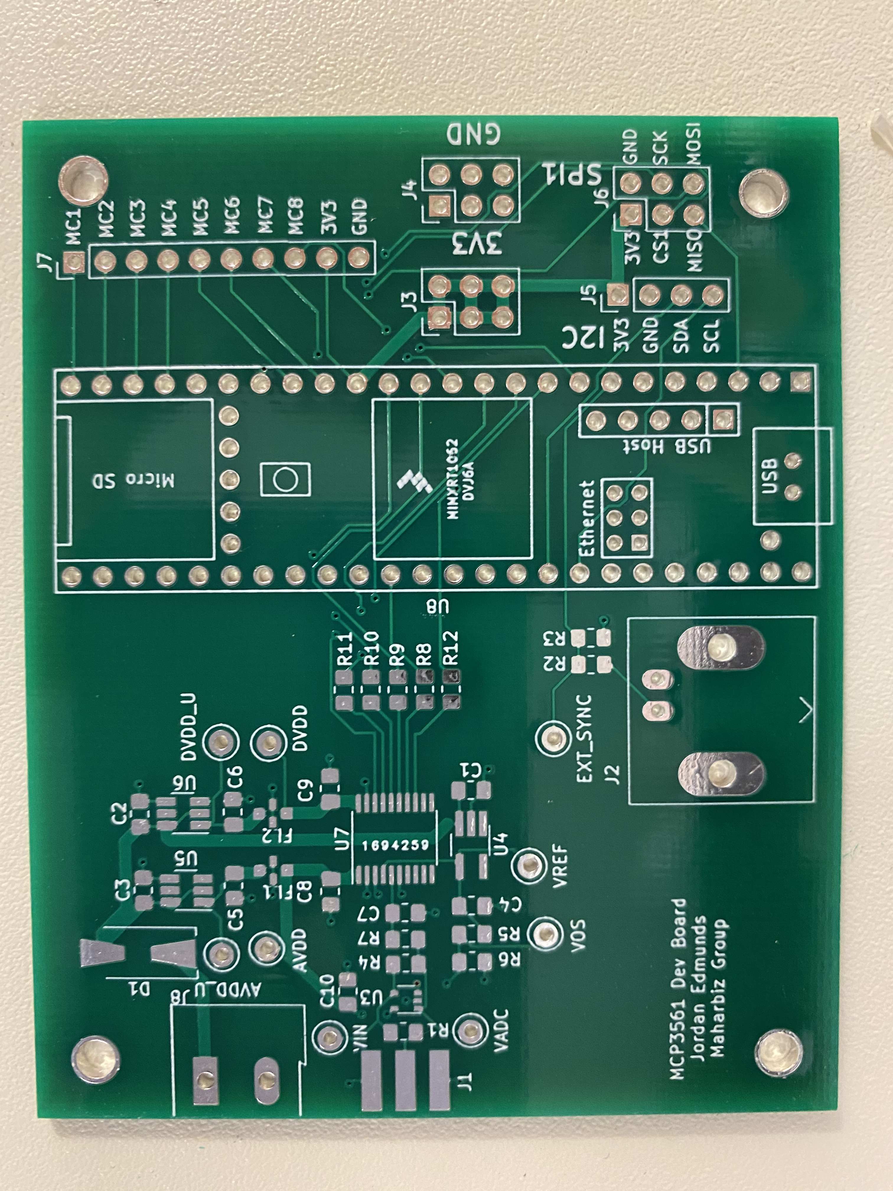
Development board for the MCP3561 ADC
MCP3561DevBoard is an open-source printed circuit board by edmundsj, from the edmundsj/MCP3561DevBoard repository on GitHub. It is a 2-layer board of 81.3 × 66 mm with 52 parts on 97 nets, routed with 336 tracks and 41 vias.
It is built around the TEENSY 4.1 and MCP3561-E/NC. Its parts include 12 resistors, 10 capacitors, 8 connectors, 6 ICs and 1 diode. It belongs with the NXP (LPC, Kinetis, i.MX RT) boards of this library.


Development board for MCP3561 ADC, a <153kSpS sigma-delta (oversampling) ADC capable of ~108dB SNR.
Measured with MCLK=10MHz, OSR=256, fs=9.76kHz, Av=1
Measured with MCLK=10MHz, OSR=256, fs=9.76kHz, Av=10
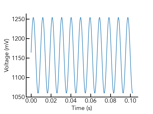
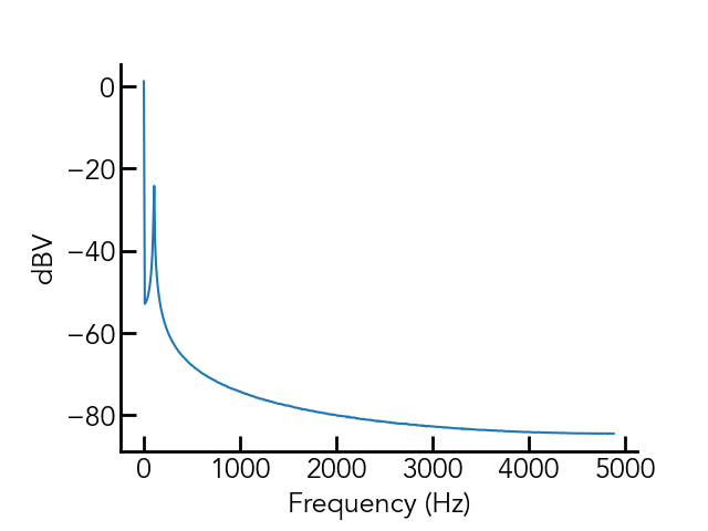
Fig. 3 and 4 show the same plots with an input signal of 10mVrms (Av=10) at 105Hz.
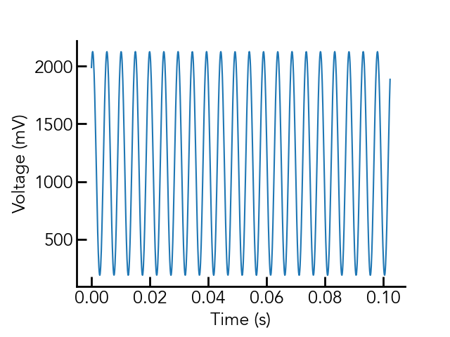
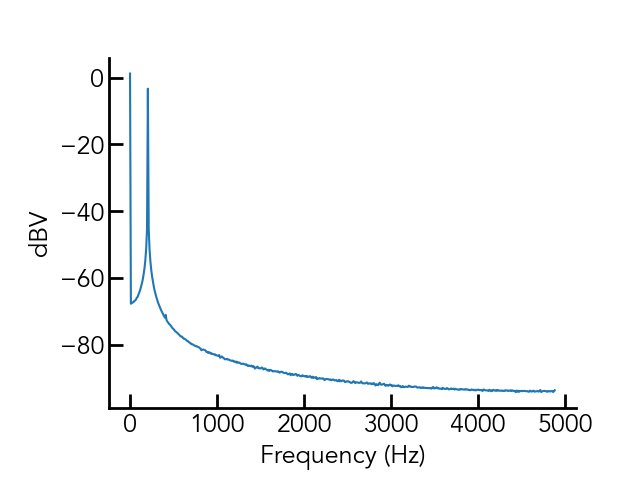
Fig. 5 and 6 show the same plots with an input signal of 100mVrms (Av=10) at 205Hz.
Using this dev board requires you have python installed on your computer, as
well as the Teensyduino IDE. You must then upload the code in arduino_code/
to the Teensy being used for measurement, which I have written to communicate
via the arduino Serial() interface (USB) using the SCPI language. Feel free
to communicate with it using your own scripts, but I have written a python
implementation which can be found in MCP3561.py
here.
| Qty | Value | Footprint | References |
|---|---|---|---|
| 9 | 470nF | Capacitor_SMD:C_0805_2012Metric_Pad1.15x1.40mm_HandSolder | C1, C2, C3, C4, C5, C6, C8, C9, C10 |
| 4 | 10R | Resistor_SMD:R_0805_2012Metric_Pad1.15x1.40mm_HandSolder | R8, R9, R10, R11 |
| 4 | MountingHole | my_library_foot:m3_mounting_hole | H1, H2, H3, H4 |
| 3 | Conn_02x03_Counter_Clockwise | Connector_PinHeader_2.54mm:PinHeader_2x03_P2.54mm_Vertical | J3, J4, J6 |
| 2 | 10k | Resistor_SMD:R_0805_2012Metric_Pad1.15x1.40mm_HandSolder | R1, R4 |
| 2 | 1k | Resistor_SMD:R_0805_2012Metric_Pad1.15x1.40mm_HandSolder | R3, R6 |
| 2 | ADP3330-X | Package_TO_SOT_SMD:SOT-23-6_Handsoldering | U5, U6 |
| 2 | EMI_Filter_LCL | my_library_foot:0805_3TERM | FL1, FL2 |
| 1 | 100R | Resistor_SMD:R_0805_2012Metric_Pad1.15x1.40mm_HandSolder | R7 |
| 1 | 100nF | Capacitor_SMD:C_0805_2012Metric_Pad1.15x1.40mm_HandSolder | C7 |
| 1 | 320R | Resistor_SMD:R_0805_2012Metric_Pad1.15x1.40mm_HandSolder | R2 |
| 1 | 3k | Resistor_SMD:R_0805_2012Metric_Pad1.15x1.40mm_HandSolder | R5 |
| 1 | ADR366 | Package_TO_SOT_SMD:TSOT-23-5_HandSoldering | U4 |
| 1 | AVDD | my_library_foot:TestPoint_Keystone_5000-5004_Miniature | TP7 |
| 1 | AVDD_U | my_library_foot:TestPoint_Keystone_5000-5004_Miniature | TP5 |
| 1 | Conn_01x04 | Connector_PinHeader_2.54mm:PinHeader_1x04_P2.54mm_Vertical | J5 |
| 1 | Conn_01x10_Male | Connector_PinHeader_2.54mm:PinHeader_1x10_P2.54mm_Vertical | J7 |
| 1 | Conn_Coaxial | my_library_foot:BNC_JACK_RA | J2 |
| 1 | Conn_Coaxial | my_library_foot:CON-SMA-EDGE-S | J1 |
| 1 | DIODE | Diode_SMD:D_SMA-SMB_Universal_Handsoldering | D1 |
| 1 | DVDD | my_library_foot:TestPoint_Keystone_5000-5004_Miniature | TP8 |
| 1 | DVDD_U | my_library_foot:TestPoint_Keystone_5000-5004_Miniature | TP6 |
| 1 | EXT_SYNC | my_library_foot:TestPoint_Keystone_5000-5004_Miniature | TP9 |
| 1 | MCP3561 | Package_SO:TSSOP-20_4.4x6.5mm_P0.65mm | U7 |
| 1 | R_US | Resistor_SMD:R_0805_2012Metric_Pad1.15x1.40mm_HandSolder | R12 |
| 1 | Screw_Terminal_01x02 | TerminalBlock:TerminalBlock_Altech_AK300-2_P5.00mm | J8 |
| 1 | TLV9051 | Package_TO_SOT_SMD:SOT-353_SC-70-5 | U3 |
| 1 | Teensy4.1 | teensy:Teensy41 | U8 |
| 1 | VADC | my_library_foot:TestPoint_Keystone_5000-5004_Miniature | TP3 |
| 1 | VIN | my_library_foot:TestPoint_Keystone_5000-5004_Miniature | TP2 |
| 1 | VOS | my_library_foot:TestPoint_Keystone_5000-5004_Miniature | TP1 |
| 1 | VREF | my_library_foot:TestPoint_Keystone_5000-5004_Miniature | TP4 |

KLFAMO/relock_Artiq
This project is an electronic device based on the STM32 microcontroller, equipped with an Ethernet port for remote control and data communication.

UoM-Robotics-Society/ROV-project
Software, mechanical design and hardware for ROV

newdigate/teensy-eurorack
Hardware Design: Eurorack shield for teensy 4.1 with 14 in / 16 out analog channels


It measures 81.3 × 66 mm and has 2 copper layers, 1.6 mm thick.
52 parts, built around the TEENSY 4.1 and MCP3561-E/NC. The full list of its parts is on this page, with links to each part's symbol and footprint where PCBKit's library has them.
From the edmundsj/MCP3561DevBoard repository on GitHub, at the commit this page was made from: the board is kicad/MCP3561DevBoard.kicad_pcb. PCBKit opens the board in the browser, with nothing to install.
Its repository states no licence, so its author keeps all rights: ask edmundsj before reusing the design.