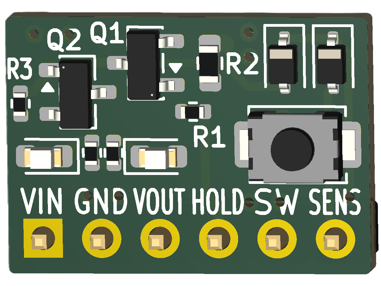
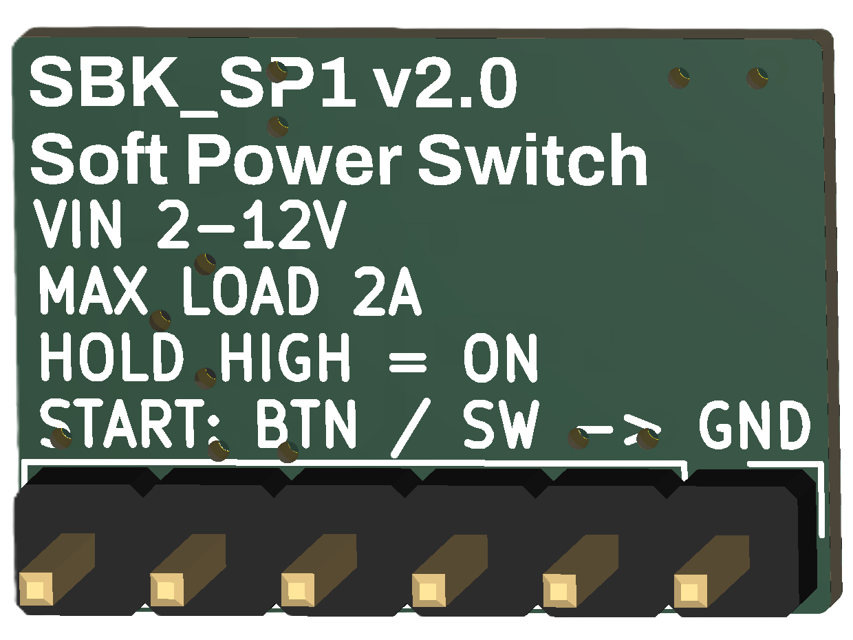
SBK SP1 is an open-source printed circuit board by sbarabe, from the sbarabe/SBK_SP1 repository on GitHub, published under the CERN-OHL-P-2.0 licence. It is a 2-layer board of 15.7 × 11.1 mm with 13 parts on 10 nets, routed with 27 tracks and 12 vias.
It is built around the AO3400A, AO3401A and TS-1088-AR02016. Its parts include 5 resistors, 4 diodes, 2 transistors, 1 connector and 1 switch. It belongs with the power boards of this library.
Open-source soft power switch module for learning and embedded electronics projects.
SBK_SP1 is a compact, reusable soft power switch module for battery-powered and low-voltage embedded systems.
A momentary push button, maintained switch, or external control can turn the system on. Once powered, a microcontroller can assert the HOLD input to keep the system running independently of the switch state.
Version 2.0 adds an onboard start button, a dedicated external SW input, and an independent SENS output. This allows the microcontroller to continue monitoring the external switch while holding its own power on, making graceful software-controlled shutdown possible.
Designed for breadboards, prototypes, and educational projects, SBK_SP1 provides an easy way to add soft power management to Arduino, ESP32, RP2040, ATtiny, STM32, and similar microcontroller-based systems.
Features
Input voltage: 2–12 VDC
Load current: up to 2 A
High-side P-channel MOSFET switching
MCU-controlled soft power latch
Onboard power/start button
External momentary button or maintained switch input
Independent switch-state sensing
Supports graceful MCU-controlled shutdown
Ultra-low off-state current (< 1 µA typ.)
Power input and output status LEDs
Breadboard-friendly 2.54 mm pin header
Open-source hardware
Optimized for low-cost assembly using JLCPCB Basic components
Specifications
Parameter
Specification
Input voltage
2–12 VDC
Maximum load
2 A
Off-state current
< 1 µA typical
HOLD input
Active HIGH, 2 V–VIN
SW input
Active LOW, connect to GND
SENS output
Active LOW, external/MCU pull-up required
PCB size
15.8 × 11.2 mm
Pinout
Pin
Description
VIN
Power input (2–12 VDC)
GND
Ground
VOUT
Switched power output
HOLD
Active-HIGH MCU power-hold input. Drive HIGH (2 V–VIN) to keep VOUT enabled.
SW
Active-LOW external switch input. Connect to GND to start/activate the module.
SENS
Active-LOW switch-sense output. Connect to an MCU input with an internal or external pull-up.
The onboard push button is connected to the SW and SENS functions and can be used to start the module without an external switch.
Typical Application
text
Battery / Power Supply
         │
         │
        VIN
   ┌───────────┐
   │  SBK_SP1  │
   │           │
   │   VOUT    ├──────────> Embedded System Power
   │           │
MCU├─ HOLD <───┤ MCU output
   │           │
MCU├─ SENS ───>│ MCU input with pull-up
   │           │
   │    SW     ├──── Switch / Push Button ──── GND
   └───────────┘
         │
        GND
Operation
Power On
The user presses the onboard button or connects SW to GND.
The hardware immediately enables the high-side power MOSFET.
VOUT powers the microcontroller and load.
SENS goes LOW, allowing the microcontroller to detect the active switch.
The microcontroller boots and drives HOLD HIGH.
The module remains powered after a momentary button is released.
Power Hold
While HOLD is HIGH, the microcontroller keeps VOUT enabled independently of the state of SW.
Because SENS monitors the switch separately from the HOLD circuit, the microcontroller can continue detecting button presses, button releases, or changes in a maintained external switch while power remains latched.
Graceful Shutdown
With a maintained ON/OFF switch, SBK_SP1 can support a software-controlled shutdown sequence:
The external switch connects SW to GND to start the system.
The microcontroller boots and drives HOLD HIGH.
The user opens the external switch.
SENS returns HIGH while HOLD keeps the system powered.
The microcontroller detects the switch change and performs any required shutdown tasks.
When shutdown is complete, the microcontroller drives HOLD LOW.
SBK_SP1 disconnects VOUT from the load.
This allows firmware to save data, stop peripherals, or perform other cleanup before removing power.
Using a Momentary Push Button
SBK_SP1 can also be used with a conventional momentary push button.
Connect the external button between SW and GND, or simply use the onboard button.
A button press starts the system and pulls SENS LOW. The microcontroller can then assert HOLD to keep itself powered after the button is released.
Because SENS remains independent of HOLD, the same button can continue to be monitored by the firmware while the system is running.
Applications
Microcontroller platforms
Arduino
ESP32
RP2040
ATtiny
STM32
Example applications
Portable instruments
Battery-powered sensors
Educational electronics projects
Custom embedded devices
Notes
HOLD is an active-HIGH input and should not exceed VIN.
SW is an active-LOW input and is activated by connecting it to GND.
SENS is an active-LOW sense signal and requires an external or MCU internal pull-up.
The onboard push button and external SW input operate in parallel.
Do not apply an external positive voltage directly to SW.
Inductive loads require an external flyback diode or equivalent protection.
High-capacitance loads may require inrush-current limiting.
The 2 A rating is the maximum recommended module load; consider wiring, connector, thermal, and application conditions when operating near the maximum current.
Getting Started
This project is fully open-source hardware. You can:
Build your own module using the provided KiCad design files.
Modify the design to suit your application.
Manufacture your own boards.
Assembled Modules
If you prefer a ready-to-use module, fully assembled SBK_SP1 boards may be available in small batches on demand.
For availability, pricing, or quantity inquiries, contact:
These modules are intended for hobbyists, educators, prototypes, and small-scale projects. Availability depends on component stock and production capacity.
MémoBot – Educational memory game built using SBK_SP1 and SBK_RP1
Contributing
Suggestions, bug reports, and improvements are welcome.
To report a problem or suggest an improvement, open an Issue. Pull Requests are also welcome for corrections, documentation improvements, and design changes that make the project easier to understand or build.
Support the Project
If this project is useful for learning, teaching, or prototyping, you can support its continued development.
Donations help fund prototype hardware, documentation, educational resources, and future open-source projects.
It measures 15.7 × 11.1 mm and has 2 copper layers, 1.6 mm thick.
What parts does the SBK SP1 use?
13 parts, built around the AO3400A, AO3401A and TS-1088-AR02016. The full list of its parts is on this page, with links to each part's symbol and footprint where PCBKit's library has them.
Where can I download the SBK SP1 KiCad files?
From the sbarabe/SBK_SP1 repository on GitHub, at the commit this page was made from: the board is hardware/KiCad/SBK_SP1.kicad_pcb and its schematic hardware/KiCad/SBK_SP1.kicad_sch. PCBKit opens the board in the browser, with nothing to install.
Can I use the SBK SP1 design in my own project?
Its repository publishes it under the CERN-OHL-P-2.0 licence: you may reuse it on that licence's terms (keep the author's notice, and for a copyleft licence share your changes alike).
Home Assistant Smart Home Alarm Control Panel with fingerprint reader, NFC/RFID card reader, motion radar, and touchscreen TFT display. It can control your smart home, not just your home security system.