2 layers33 × 22.5 mm
Tick
jkramarz/TheTick
The Tick is the next evolution in covert access control system implants for simulating adversary-in-the-middle attacks.
37 parts183GPL-3.0

 Sarbf1/Sensor-to-CAN1
A HAT for Arduino nano, to Connect nearly any sensor and send its walues using CAN or NMEA bus
Nano CAN Sense HAT is an open-source printed circuit board by Sarbf1, from the Sarbf1/Sensor-to-CAN repository on GitHub. It is a 4-layer board of 46 × 20 mm with 51 parts on 53 nets, routed with 416 tracks and 170 vias.
It is built around the NCS20074DTB and NUP2105L. Its parts include 17 resistors, 10 capacitors, 6 diodes, 6 connectors and 4 ICs. It belongs with the interfaces and adapters boards of this library.


A HAT for Arduino nano, to Connect nearly any sensor and send its walues using CAN or NMEA bus
This is an early version. The hardware is drwan, but not checked or tested. The four layer board is slightly larger than the arduino nano R4, as i have added a shield ring (in case of use in high EMV areas such as in electric vehicles).
Also the code has not been written yet, but will follow.
The goal is to have a HAT board for on a Arduino Nano R4, that can connect to any sensor (3.3V 500mA, 5V 1A or Vin). The sensor vaule (any voltage, or current input, selectable with a jumper) is processed by the arduino R4 and the sent using CANbus, using NMEA2000 protocol. It has three LEDs that can be configured (currentls intended to show TX, RX and Erros) and two buttons, of wich one is used as Arduino Reset.
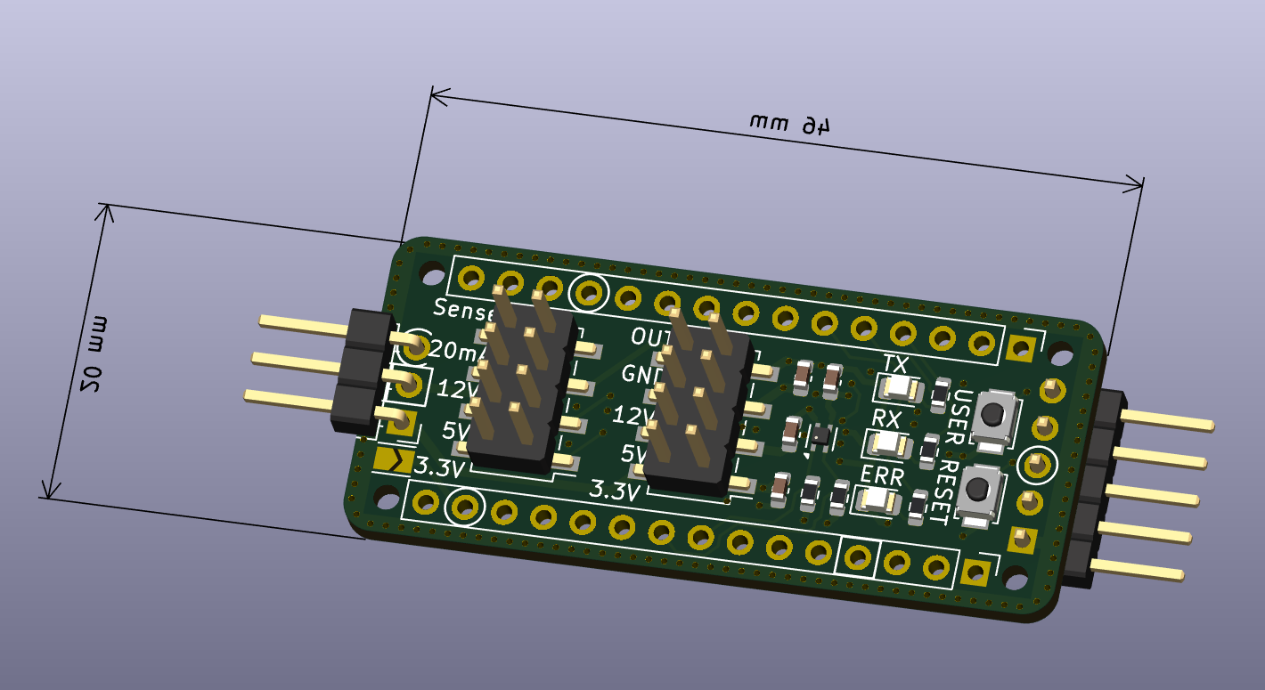
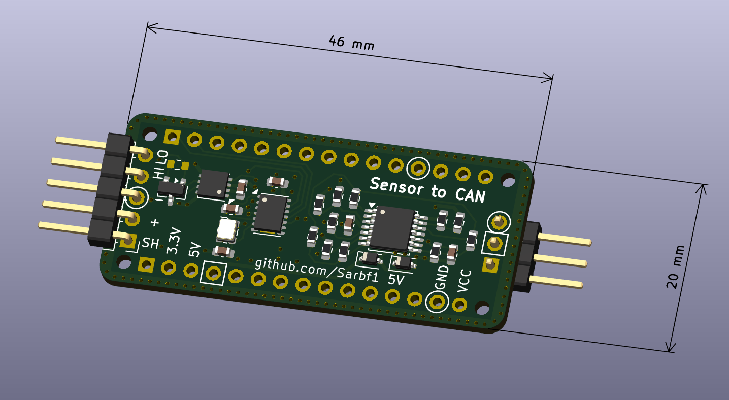
| Qty | Value | Footprint | References |
|---|---|---|---|
| 12 | 1kR | Resistor_SMD:R_0603_1608Metric | R1, R2, R3, R4, R8, R9, R10, R11, R13, R14, R15, R18 |
| 8 | 100nC | Capacitor_SMD:C_0603_1608Metric | C2, C3, C4, C5, C6, C7, C10, C11 |
| 4 | MountingHole_65mil | Arduino_MountingHole:MountingHole_65mil | MH1, MH2, MH3, MH4 |
| 3 | 2kR | Resistor_SMD:R_0603_1608Metric | R5, R7, R12 |
| 3 | LED | LED_SMD:LED_0805_2012Metric | D1, D2, D3 |
| 2 | 8pC | Capacitor_SMD:C_0603_1608Metric | C8, C9 |
| 2 | Conn_02x04_Counter_Clockwise | Connector_PinHeader_2.54mm:PinHeader_2x04_P2.54mm_Vertical_SMD | J3, J4 |
| 2 | D_Zener_5.1V | Diode_SMD:D_SOD-323 | D5, D6 |
| 2 | SW_Push | Button_Switch_SMD:SW_SPST_B3U-1000P | SW1, SW2 |
| 1 | 120R | Resistor_SMD:R_0603_1608Metric | R16 |
| 1 | 250R | Resistor_SMD:R_0603_1608Metric | R17 |
| 1 | Analog | Connector_PinHeader_2.54mm:PinHeader_1x15_P2.54mm_Vertical | J1 |
| 1 | Conn_01x03 | Connector_PinHeader_2.54mm:PinHeader_1x03_P2.54mm_Horizontal | J6 |
| 1 | Conn_01x05 | Connector_PinHeader_2.54mm:PinHeader_1x05_P2.54mm_Horizontal | J5 |
| 1 | Digital | Connector_PinHeader_2.54mm:PinHeader_1x15_P2.54mm_Vertical | J2 |
| 1 | ECS-200-8-33 | Oscillator:Oscillator_SMD_ECS_2520MV-xxx-xx-4Pin_2.5x2.0mm | Y2 |
| 1 | MCP2518FD-xQBB | Package_DFN_QFN:DFN-14-1EP_3x4.5mm_P0.65mm_EP1.65x4.25mm | U2 |
| 1 | MCP2542FDxMF | Package_DFN_QFN:DFN-8-1EP_3x3mm_P0.65mm_EP1.55x2.4mm | U3 |
| 1 | NCS20074DTB | Package_SO:TSSOP-14_4.4x5mm_P0.65mm | U1 |
| 1 | NUP2105L | Package_TO_SOT_SMD:SOT-23 | D4 |
| 1 | SHT4x | Sensor_Humidity:Sensirion_DFN-4_1.5x1.5mm_P0.8mm_SHT4x_NoCentralPad | U4 |
| 1 | SolderJumper_2_Open | Jumper:SolderJumper-2_P1.3mm_Open_TrianglePad1.0x1.5mm | JP1 |
It measures 46 × 20 mm and has 4 copper layers, 1.6 mm thick.
51 parts, built around the NCS20074DTB and NUP2105L. The full list of its parts is on this page, with links to each part's symbol and footprint where PCBKit's library has them.
From the Sarbf1/Sensor-to-CAN repository on GitHub, at the commit this page was made from: the board is Nano-CAN-Sense-HAT_Board/Nano-CAN-Sense-HAT.kicad_pcb and its schematic Nano-CAN-Sense-HAT_Board/Nano-CAN-Sense-HAT.kicad_sch. PCBKit opens the board in the browser, with nothing to install.
Its repository states no licence, so its author keeps all rights: ask Sarbf1 before reusing the design.
jkramarz/TheTick
The Tick is the next evolution in covert access control system implants for simulating adversary-in-the-middle attacks.


fake-name/cfs-reverse-engineering
Reverse engineering the Creality CFS for use as a general AMU/MMU system


rusefi/uaefi
🔴Community support ONLY 🔴 https://www.facebook.com/groups/rusEfi 🔴 Discord🔴 Commercial Support 🔴
