Skip to the content
PCBKitNew board
4 layers100 × 100 mmUaefi, the printed circuit board in 3D

🔴Community support ONLY 🔴 https://www.facebook.com/groups/rusEfi 🔴 Discord🔴 Commercial Support 🔴

Size
100 × 100 mm
Copper layers
4
Thickness
1.6 mm
Parts
171
Nets
240
Pads
972
Tracks, vias
1,765, 376
Pours
7
Routed
Yes
KiCad
KiCad 8.0 (file 20240108)
Created
11 Sep 2023
Updated
30 Oct 2026

Overview

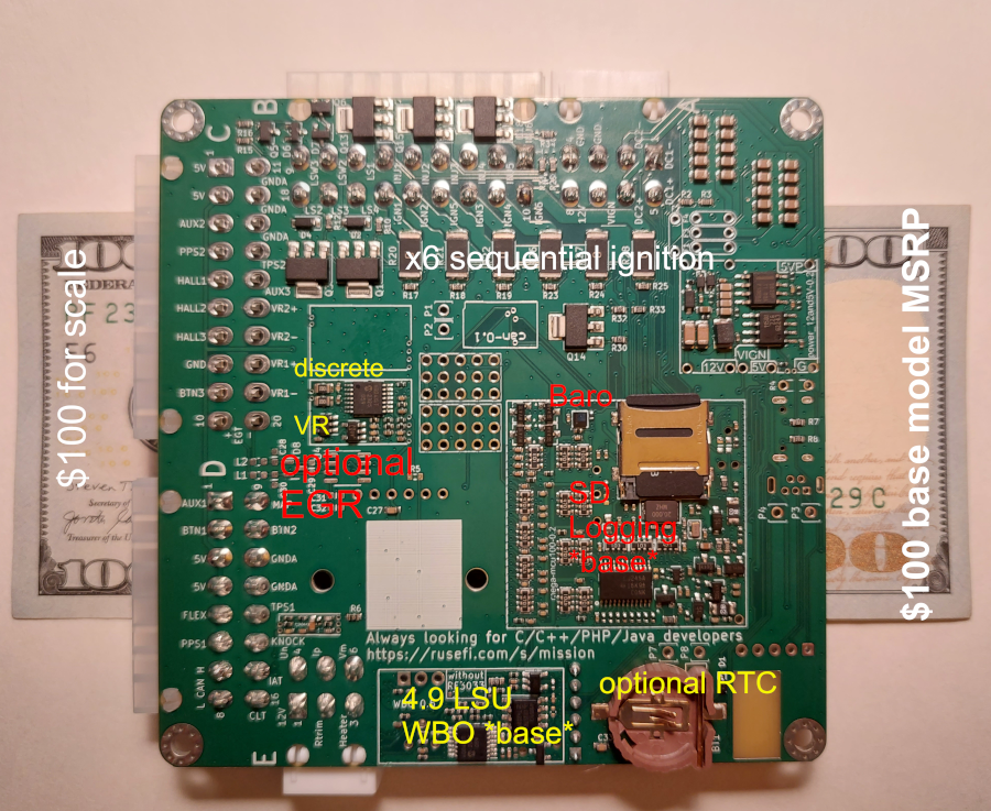
Uaefi is an open-source printed circuit board by rusefi, from the rusefi/uaefi repository on GitHub. It is a 4-layer board of 100 × 100 mm with 171 parts on 240 nets, routed with 1,765 tracks and 376 vias.

It is built around the ISL9V3040D3ST, TLE9201SG and MAX31855KASA+T, with the VNLD5160TR-E, B5819W and 1N4148WS among its other parts. Its parts include 51 resistors, 35 connectors, 33 capacitors, 11 ICs and 10 fuses.

Main components

8

README

README.md

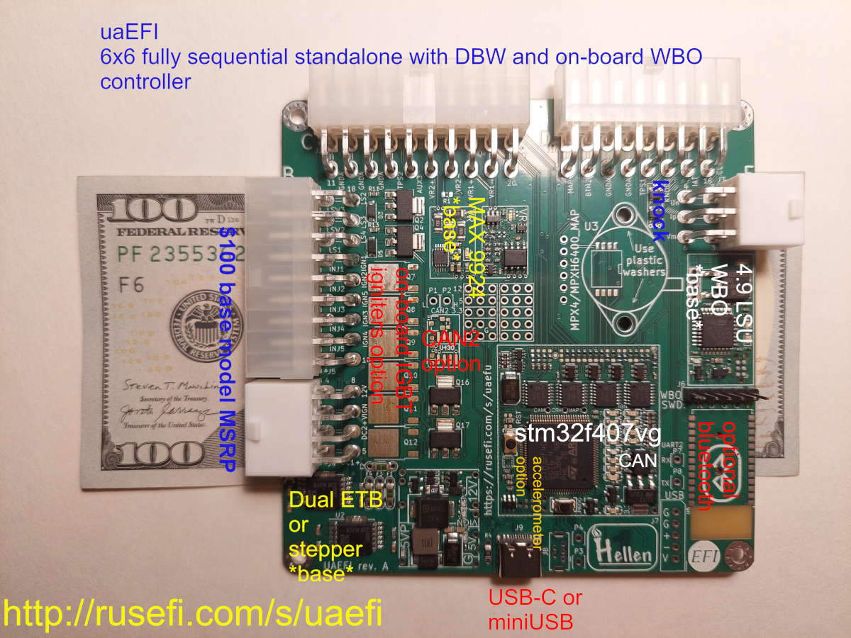
Ultra Affordable EFI

🟢$275 base model rusEFI store🟢

Community Support

🔴Community support ONLY 🔴 https://www.facebook.com/groups/rusEfi 🔴 Discord🔴 Commercial Support 🔴

Technical Details

Open Source KiCAD hardware powered by Hellen-One

Powered by rusEFI firmware

User Documentation
x

x

MCU options

1mb of flash is required.

One day we shall try https://jlcpcb.com/partdetail/Stmicroelectronics-STM32F427VIT6%2FC57097#EC or https://jlcpcb.com/partdetail/Stmicroelectronics-STM32F437VIT7%2FC1338578#EC

HOWTO JLCPCB

You would need three files from boards/uaefi-a/board folder to place your JLCPB Assembly order: gerber.zip BOM-JLC.csv and CPL.csv

Q: having trouble with opening uaefi board project. library path seems ok, i do not know how to solve missing modules issue

A: missing modules are closed source. they are filled in by github magic github magic combines gerbers and spits out a complete bom/pcl/new gerbers to upload to jlc/friends. See https://github.com/rusefi/hellen-one/tree/master?tab=readme-ov-file#tldr for more info

Q: Magic modules? How do I see schematics of those?

A: https://github.com/rusefi/hellen-one has full documentation for each module

Q: Something wrong with BOM?

A: Nope, that's normal nothing to worry about click 'Continue'.

image

Q: how do I get more RAM for Lua?

A: fabricate with STM32F42xVI firmware would defect extra RAM and give you extra Lua. Once your script does not fit into STM32F42xVI it's F7 time or help us leverage F413.

Q: I've place an order with JLCPCB and I see scary looking wrong orientation?

A: that's expected. See boards/uaefi-c/board Original*.png files and Produce*.png after JLCPCB manual review process.

Bluetooth power issue fix

It was found that board with installed BT module may be affected by power issue.

During power on BT module consume too much inrush current on 3.3V line causing 3.3V drop below MCU reset hreshold. This may lead to unstable start or infinity reset loop.

To fix this please install additional capacitors to 5V and 3.3V powerlines.

Polarized electrolytic capacitors with at least 10V rating and extended temperature range are recommended. Tantalum and solid electrolytic capacitors are also suitable.

Please carefully follow illustrated polarity.

33..47uF should be added to 5V powerrail. This or this or any of these.

photo_2025-10-21_10-22-45

And 220..470uF should be added to 3.3V powerrail. This or this or any of these.

photo_2025-10-21_10-22-50

HOWTO EGT chip

This board has a placeholder for MAX31855 (or MAX6675) termocouple-to-digital chip. This chip is not populated by default!

Screenshot from 2025-09-26 11-15-15

D8 is optional ESD protection and also is not populated by default. You need to solder U4 only, D8 is optional. All passive components are already populated.

MAX31855 works without addtional modification.

For MAX6675 connect EGT- to GNDA either on J2 "C" connector or just short C28 (replace with 0R).

Screenshot from 2025-09-26 11-19-41

[EXPERIMENTAL] How to make MAX9924 work with low tooth count trigger wheel

In some cases user may need two VR inputs on UAEFI and both trigger wheels are low-tooth count.

In default configuration MAX9924 does not work with low count trigger wheels because of its "adaptive peak threshold" and its watchdog.

Screenshot from 2025-10-12 16-58-30

On UAEFI MAX9924 is configured in A2 mode.

Screenshot from 2025-10-12 16-59-49

B mode allow use of MAX9924 with low count trigger wheels. But external Bias and Thresholt voltages should be allpied. Both can be sources from UAEFI Discrete VR module.

List of modifications:

  1. pin 6: ZERO_EN connect to VCC instead of GND.
  2. pin 4: supply 2.5 V instead of GND
  3. pin 8: EXT, supply external threshold voltage

Pins 4 and 6 needs to be lifted from PCB to be disconnected from GND. Pin 8 initially is not connected to any circuit.

Use hot air gun to de-solder whole chip. Then twist pins 4 and 6 up so both do not touch PCB. Then solder chip back to PCB

Now use thin wire to connect:

  1. pin 6 to pin 10 of the same chip.
  2. pin 4 to Vref at R769 + C754. See iBOM for its locations
  3. pin 8 to thresh_high at U756 pin 1. See iBOM for its locations

photo_2025-10-12_11-40-24

Now MAX9924 VR input uses same threshold vs RPM settings that is set for Descrete VR input. And it is cabable to work with low tooth count trigger wheels without noise issues.

Parts

171
QtyValueFootprintReferences
274.7khellen-one-common:R0603R1, R4, R10, R11, R12, R13, R14, R15, R16, R29, R30, R31, R32, R33, R34, R41 +11
2010uhellen-one-common:C0805C1, C2, C3, C4, C5, C10, C14, C15, C16, C17, C18, C19, C20, C21, C22, C23 +4
14Conn_02x02_Odd_EvenConnector_PinSocket_2.54mm:PinSocket_2x02_P2.54mm_VerticalJ1, J11, J12, J13, J14, J15, J16, J17, J18, J19, J20, J21, J22, J24
12Padhellen-one-common:PAD-THP1, P2, P3, P4, P5, P6, P7, P8, P15, P16, P17, P18
60Resistor_SMD:R_2512_6332MetricR20, R21, R22, R26, R27, R28
6100nhellen-one-common:C0603C11, C24, C27, C29, C31, C33
610nhellen-one-common:C0603C12, C13, C25, C26, C28, C30
622hellen-one-common:R0603R17, R18, R19, R23, R24, R25
650mAFuse:Fuse_0603_1608MetricF5, F6, F7, F8, F9, F10
6ISL9V3040D3STPackage_TO_SOT_SMD:TO-252-2Q7, Q8, Q9, Q10, Q11, Q12
6VNLD5160TR-EPackage_SO:SOIC-8_3.9x4.9mm_P1.27mmU6, U7, U8, U9, U10, U11
4B5819Whellen-one-common:SOD-123D2, D3, D4, D5
4FuseFuse:Fuse_1206_3216Metric_Pad1.42x1.75mm_HandSolderF1, F2, F3, F4
4M3MountingHole:MountingHole_3.2mm_M3_Pad_ViaH1, H2, H3, H4
310khellen-one-common:R0805R35, R36, R37
3DNPhellen-one-common:R0805R38, R39, R40
20hellen-one-common:R0603R5, R6
2470R@100MHzInductor_SMD:L_0603_1608MetricL1, L2
25.6khellen-one-common:R0603R7, R8
2PROTO_AREAhellen-one-common:PROTO_AREAG3, G4
2TLE9201SGPackage_SO:Infineon_PG-DSO-12-11U1, U2
11N4148WShellen-one-common:SOD-323D1
11uhellen-one-common:C0603C32
133khellen-one-common:R0603R2
15569-06A2Connector_Molex:Molex_Mini-Fit_Jr_5569-06A2_2x03_P4.20mm_HorizontalJ3
15569-08A2Connector_Molex:Molex_Mini-Fit_Jr_5569-08A2_2x04_P4.20mm_HorizontalJ4
15569-16A2Connector_Molex:Molex_Mini-Fit_Jr_5569-16A2_2x08_P4.20mm_HorizontalJ10
15569-18A2Connector_Molex:Molex_Mini-Fit_Jr_5569-18A2_2x09_P4.20mm_HorizontalJ5
15569-20A2Connector_Molex:Molex_Mini-Fit_Jr_5569-20A2_2x10_P4.20mm_HorizontalJ2
16.8khellen-one-common:R0603R3
1CR1220kicad6-libraries:CR1220-2BT1
1Conn_01x05_MaleConnector_Molex:Molex_SPOX_5267-05A_1x05_P2.50mm_VerticalJ7
1Conn_01x06Connector_PinHeader_2.54mm:PinHeader_1x06_P2.54mm_VerticalJ6
1JDY-33kicad6-libraries:JDY-33U5
1LOGOhellen-one-common:LOGOG2
1LOGOLOGOG***
1MAX31855KASAPackage_SO:SOIC-8_3.9x4.9mm_P1.27mmU4
1MPX4/MPXH6400_MAPkicad6-libraries:MPX-4_MAPU3
1Module-can-0.1hellen-one-can-0.1:canM7
1Module-knock-0.2hellen-one-knock-0.2:knockM2
1Module-power_12and5V-0.3hellen-one-power_12and5V-0.3:power_12and5VM1
1Module-vr-discrete-0.5hellen-one-vr-discrete-0.5:vr-discreteM3
1Module-vr-max9924-0.1hellen-one-vr-max9924-0.1:vr-max9924M4
1Module-wbo-0.6hellen-one-wbo-0.6:wboM5
1Module:mega-mcu100/0.3hellen-one-mega-mcu100-0.3:mega-mcu100M6
1NUP2105LPackage_TO_SOT_SMD:SOT-23D8
1RUSEFI_LOGOkicad6-libraries:rusefi_logoG1
1USB_B_Minihellen-one-common:USB-MINI-B-VERTICALJ8
1USB_Ckicad6-libraries:USB_CJ9

Questions

How big is the Uaefi PCB?

It measures 100 × 100 mm and has 4 copper layers, 1.6 mm thick.

What parts does the Uaefi use?

171 parts, built around the ISL9V3040D3ST, TLE9201SG, MAX31855KASA+T and VNLD5160TR-E. The full list of its parts is on this page, with links to each part's symbol and footprint where PCBKit's library has them.

Where can I download the Uaefi KiCad files?

From the rusefi/uaefi repository on GitHub, at the commit this page was made from: the board is uaefi.kicad_pcb and its schematic DC_MOTOR_0.1.kicad_sch. PCBKit opens the board in the browser, with nothing to install.

Can I use the Uaefi design in my own project?

Its repository states no licence, so its author keeps all rights: ask rusefi before reusing the design.

Similar boards

  • 4 layers102 × 107 mmHellen bremen, the printed circuit board in 3D

    Hellen bremen

    P4ulBr4ndt/hellen-bremen

    This is trying to be yet another HD ECU based on rusEFI.\ Commercial rusEFI based HD ECUs:\ https://www.nmstec.ca/product/hdrevb/ This seems to be the initial community development? https://impactwiringsolutions.com/…

    74 parts
  • 4 layers80 × 80 mmPROLT, the printed circuit board in 3D

    PROLT

    ADVecu/Hellen-PROLT

    A: .github/workflows/update-hellen-one-reference.yaml is set to pull latest hellen daily!

    95 parts
  • 4 layers86.3 × 97.1 mmHellen-112-17, the printed circuit board in 3D

    Hellen-112-17

    rusefi/hellen-112-17

    128 parts4
  • 4 layers96.5 × 114.7 mmAlphax 4ch, the printed circuit board in 3D

    Alphax 4ch

    rusefi/alphax-4chan

    Designed using KiCAD 7. Powered by Hellen One and rusEFI

    292 parts3
  • 2 layers149 × 104 mmUaBrain gm e38, the printed circuit board in 3D

    UaBrain gm e38

    rusefi/rusefi-hardware

    128 parts52
  • 4 layers160 × 75.1 mmVFRECU VR, the printed circuit board in 3D

    VFRECU VR

    VFRenjoyer/hellen-VFR800

    Hellen for 99 VFR800

    96 parts