2 layers68.3 × 94.8 mm

 samanbeer/LoRa_board
i saw a video about it. And saw how cool it is and I wanted to build custom meshtastic node and try the P2P comunication on it.
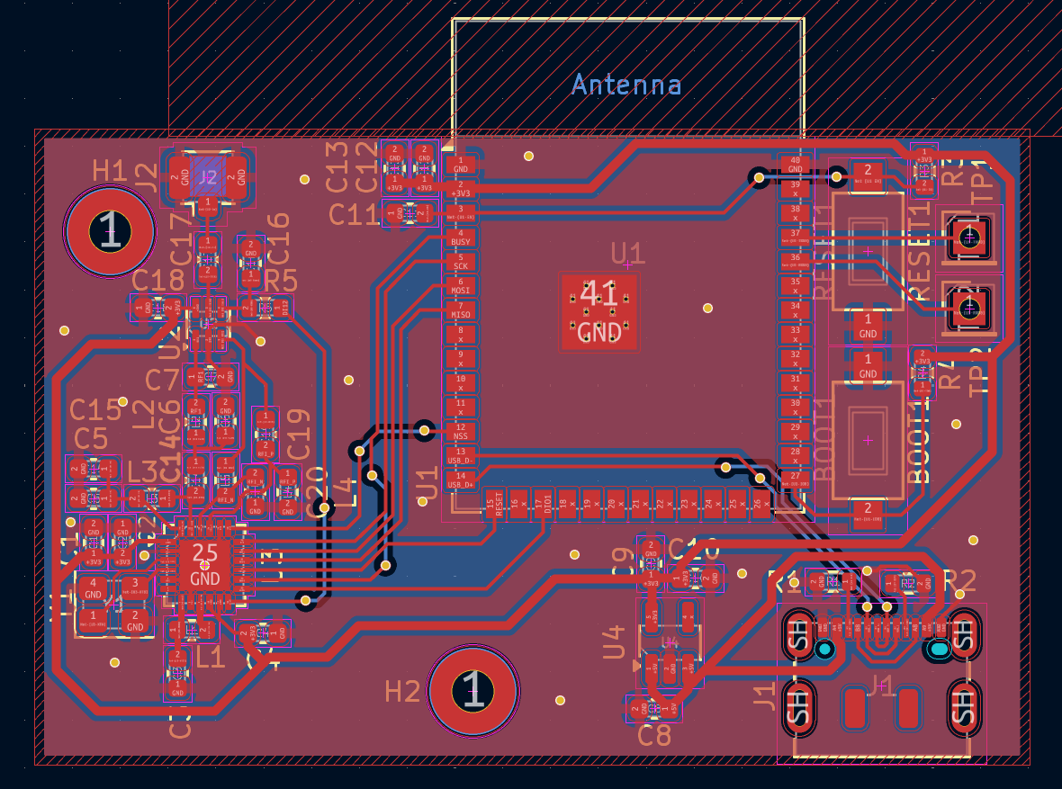
LoRa board is an open-source printed circuit board by samanbeer, from the samanbeer/LoRa_board repository on GitHub. It is a 2-layer board of 52.1 × 33.3 mm with 43 parts on 59 nets, routed with 282 tracks and 32 vias.
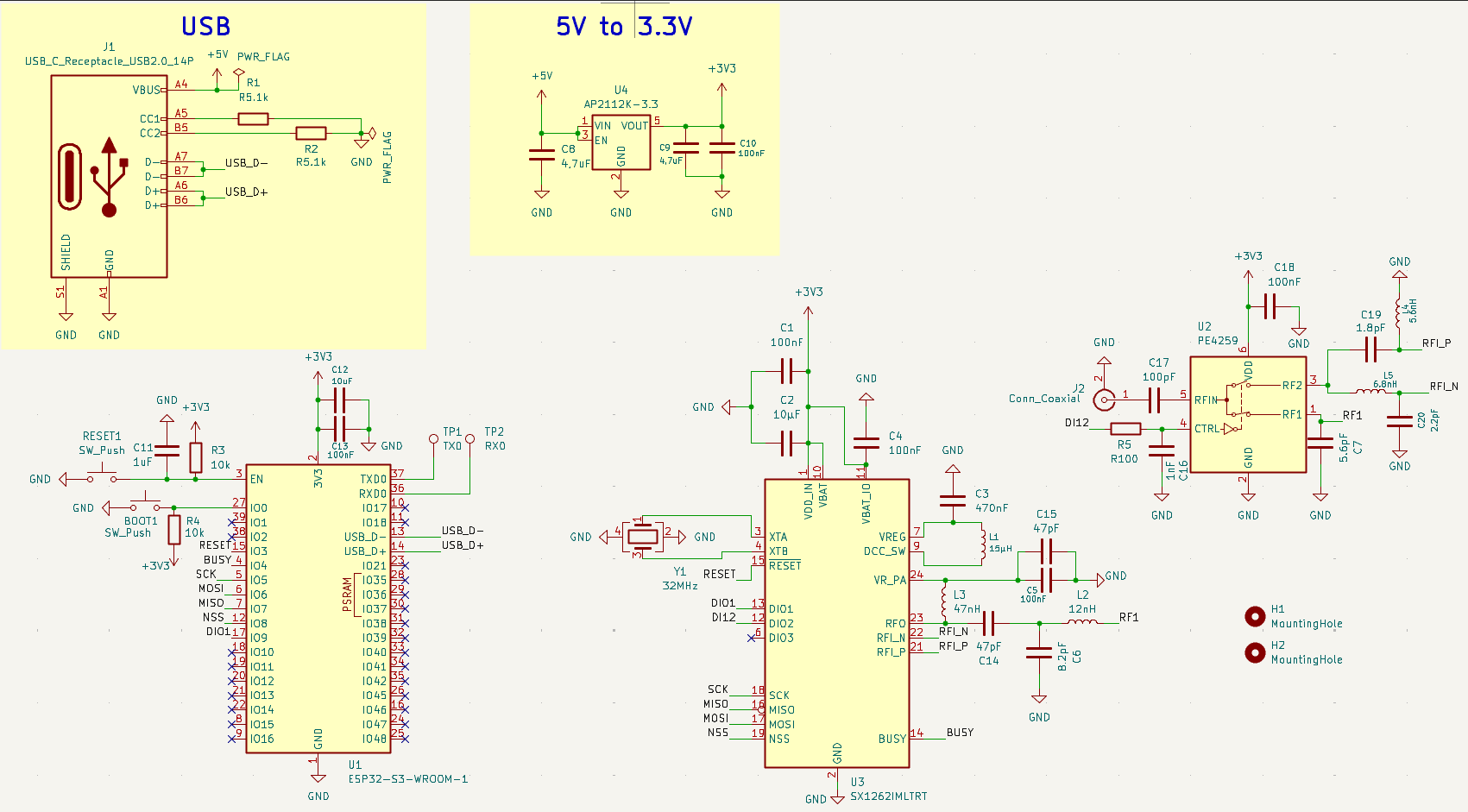
It is built around the ESP32-S3-WROOM-1-N8, PE4259-63 and SX1262IMLTRT, with the AP2112K-3.3 among its other parts. Its parts include 20 capacitors, 5 resistors, 5 inductors, 4 ICs and 2 connectors. It belongs with the radio and wireless boards and the ESP32 boards of this library.


i saw a video about it. And saw how cool it is and I wanted to build custom meshtastic node and try the P2P comunication on it.
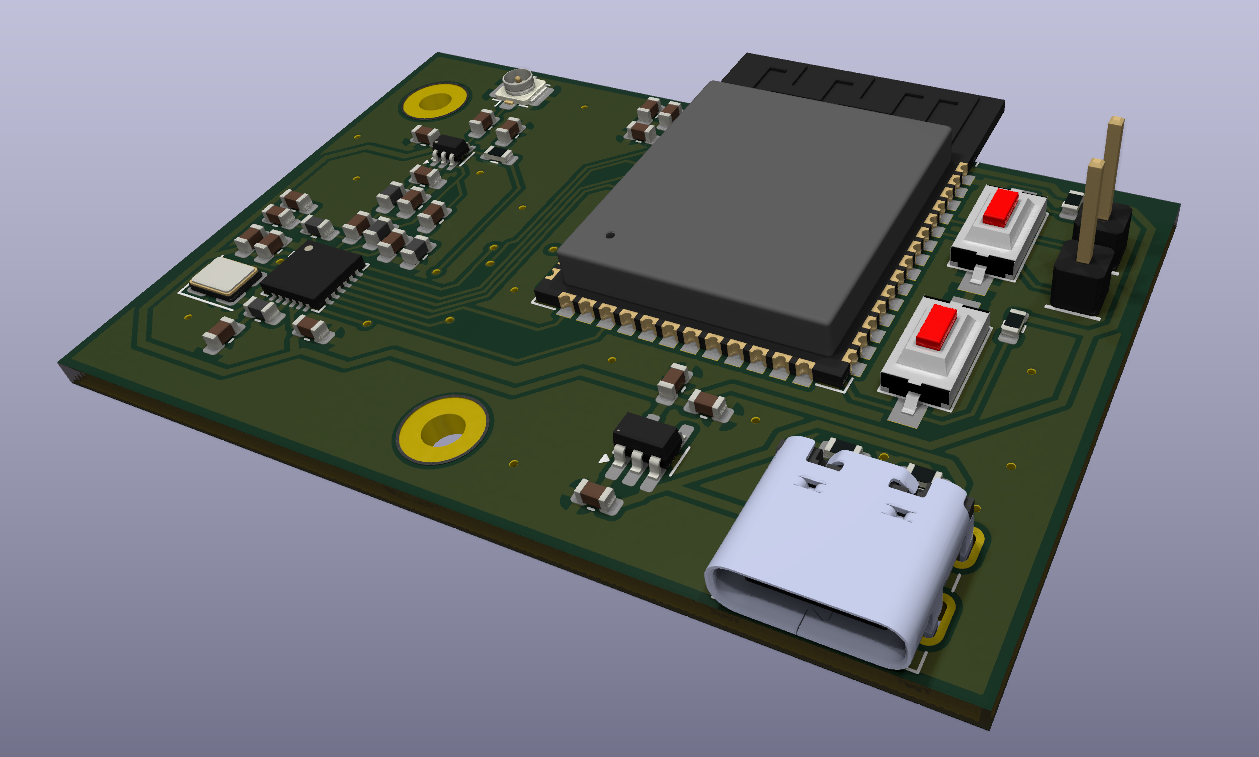
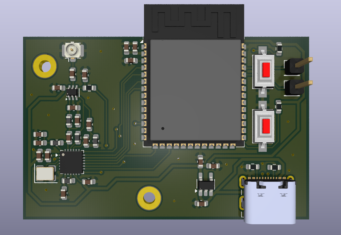
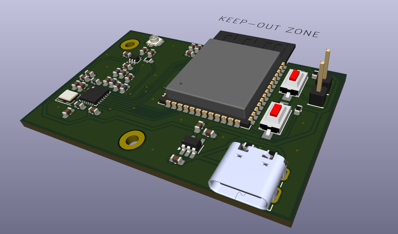
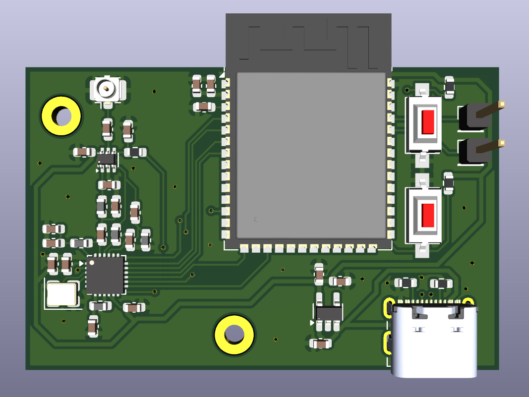
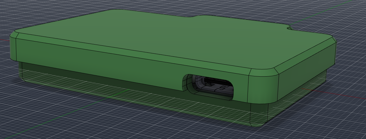
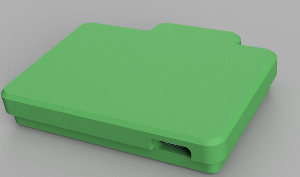
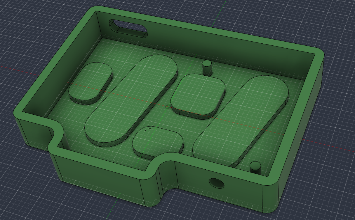
3D printable case is made in Fusion 360. All CAD and 3D model files are in the CAD/ folder.
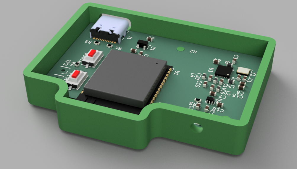
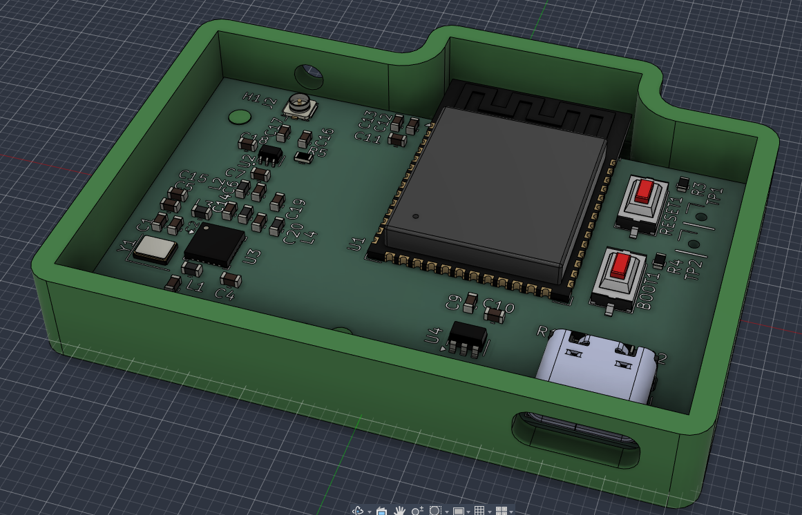
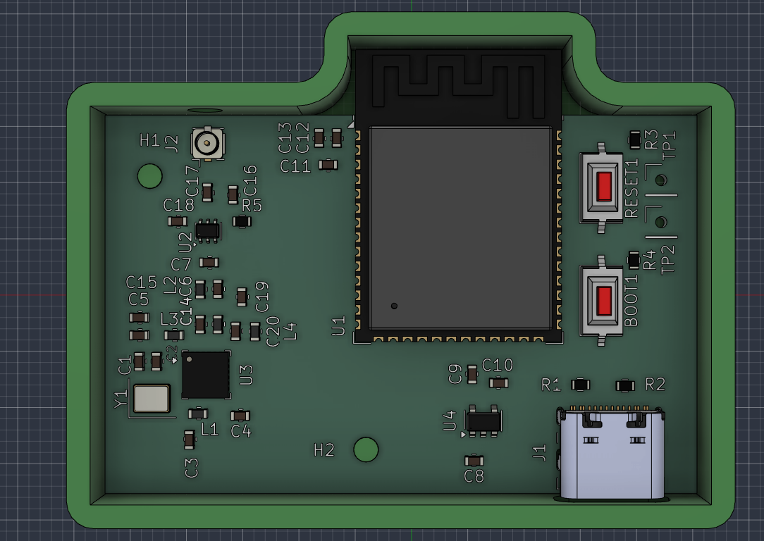
| Reference | amount | Value / Component | Footprint / Package | Link | Cost (USD, incl. VAT) |
|---|---|---|---|---|---|
| BOOT1, RESET1 | 2 | Tactile Switch (C&K RS-282G05A3-SM RT) | SMD Button (6.0x3.5mm) | Mouser Link | $1.92 |
| C1, C4, C5, C10, C13, C18 | 6 | 100nF 50V X7R (GCM188R71H104KA57J) | 0603 SMD | Mouser Link | $1.44 |
| C2, C12 | 2 | 10µF 10V X5R (C1608X5R1A106K080AC) | 0603 SMD | Mouser Link | $1.10 |
| C3 | 1 | 470nF 16V X7R (CL10B474KO8NNNC) | 0603 SMD | Mouser Link | $0.13 |
| C6 | 1 | 8.2pF 50V C0G (CC0603DRNPO9BN8R2) | 0603 SMD | Mouser Link | $0.12 |
| C7 | 1 | 5.6pF 50V C0G (CC0603DRNPO9BN5R6) | 0603 SMD | Mouser Link | $0.12 |
| C8, C9 | 2 | 4.7µF 16V X5R (C1608X5R1C475K080AC) | 0603 SMD | Mouser Link | $0.60 |
| C11 | 1 | 1µF 16V X7R (C0603C105K4RAC) | 0603 SMD | Mouser Link | $0.17 |
| C14, C15 | 2 | 47pF 50V C0G (CC0603JPNPO9BN470) | 0603 SMD | Mouser Link | $0.24 |
| C16 | 1 | 1nF 50V X7R (CL10B102KB8NNNC) | 0603 SMD | Mouser Link | $0.12 |
| C17 | 1 | 100pF 50V C0G (GRM1885C1H101JA01D) | 0603 SMD | Mouser Link | $0.13 |
| C19 | 1 | 1.8pF 50V C0G (CL10C1R8BB8NNNC) | 0603 SMD | Mouser Link | $0.12 |
| C20 | 1 | 2.2pF 50V C0G (GRM1885C1H2R2BA01D) | 0603 SMD | Mouser Link | $0.17 |
| J1 | 1 | USB-C Receptacle 16P (DX07S016JA1R1500) | USB-C 16-Pin SMD+THT | Mouser Link | $2.10 |
| J2 | 1 | U.FL Coaxial Connector (U.FL-R-SMT-1) | U.FL SMD Vertical | Mouser Link | $1.85 |
| L1 | 1 | 15µH 150mA (LQM18DH150M70L) | 0603 SMD | Mouser Link | $0.36 |
| L2 | 1 | 12nH High-Q RF (LQW18AN12NG00D) | 0603 SMD | Mouser Link | $0.16 |
| L3 | 1 | 47nH High-Q RF (LQW18AN47NG00D) | 0603 SMD | Mouser Link | $0.16 |
| L4 | 1 | 5.6nH High-Q RF (LQW18AN5N6C0ZD) | 0603 SMD | Mouser Link | $0.18 |
| L5 | 1 | 6.8nH High-Q RF (LQW18AS6N8J0ZD) | 0603 SMD | Mouser Link | $0.18 |
| R1, R2 | 2 | 5.1kΩ 1% (RC0603FR-135K1L) | 0603 SMD | Mouser Link | $0.24 |
| R3, R4 | 2 | 10kΩ 1% (RC0603FR-0710KL) | 0603 SMD | Mouser Link | $0.24 |
| R5 | 2 | 100Ω 1% (RC0603FR-07100RL) | 0603 SMD | Mouser Link | $0.24 |
| TP1, TP2 | 1 | Pin Header 1x40 (Harwin M20-9994045) | PinHeader 1x01 (2.54mm) | Mouser Link | $2.31 |
| U1 | 1 | ESP32-S3-WROOM-1-N8 (8MB Flash) | RF Module | Mouser Link | $6.79 |
| U2 | 1 | SPDT RF Switch (PE42359SCAA-Z) | SOT-363 (SC-70-6) | Mouser Link | $1.18 |
| U3 | 1 | SX1262IMLTRT LoRa Transceiver | QFN-24 (4x4mm) | Mouser Link | $10.83 |
| U4 | 1 | AP2112K-3.3TRG1 LDO 3.3V 600mA | SOT-23-5 | Mouser Link | $0.32 |
| Y1 | 1 | 32MHz Crystal (ABM8-32.000MHZ-10-B1U-T) | SMD 3225-4Pin | Mouser Link | $0.59 |
| PCB | 1 | JLCPCB | ~$10 | ||
| shipping Mouser | $33.80 | ||||
| Mouser Order | cart.XLS file [blocked] | $67.91 | |||
| Total | Cost of everything | $77.91 |
| Qty | Value | Footprint | References |
|---|---|---|---|
| 6 | 100nF | Capacitor_SMD:C_0603_1608Metric | C1, C4, C5, C10, C13, C18 |
| 2 | 10k | Resistor_SMD:R_0603_1608Metric | R3, R4 |
| 2 | 4,7uF | Capacitor_SMD:C_0603_1608Metric | C8, C9 |
| 2 | 47pF | Capacitor_SMD:C_0603_1608Metric | C14, C15 |
| 2 | MountingHole | MountingHole:MountingHole_2.2mm_M2_Pad | H1, H2 |
| 2 | R5.1k | Resistor_SMD:R_0603_1608Metric | R1, R2 |
| 2 | SW_Push | Button_Switch_SMD:SW_SPST_CK_RS282G05A3 | BOOT1, RESET1 |
| 1 | 1.8pF | Capacitor_SMD:C_0603_1608Metric | C19 |
| 1 | 100pF | Capacitor_SMD:C_0603_1608Metric | C17 |
| 1 | 10uF | Capacitor_SMD:C_0603_1608Metric | C12 |
| 1 | 10µF | Capacitor_SMD:C_0603_1608Metric | C2 |
| 1 | 12nH | Inductor_SMD:L_0603_1608Metric | L2 |
| 1 | 15µH | Inductor_SMD:L_0603_1608Metric | L1 |
| 1 | 1nF | Capacitor_SMD:C_0603_1608Metric | C16 |
| 1 | 1uF | Capacitor_SMD:C_0603_1608Metric | C11 |
| 1 | 2.2pF | Capacitor_SMD:C_0603_1608Metric | C20 |
| 1 | 32MHz | Crystal:Crystal_SMD_3225-4Pin_3.2x2.5mm | Y1 |
| 1 | 470nF | Capacitor_SMD:C_0603_1608Metric | C3 |
| 1 | 47nH | Inductor_SMD:L_0603_1608Metric | L3 |
| 1 | 5,6nH | Inductor_SMD:L_0603_1608Metric | L4 |
| 1 | 5.6pF | Capacitor_SMD:C_0603_1608Metric | C7 |
| 1 | 6.8nH | Inductor_SMD:L_0603_1608Metric | L5 |
| 1 | 8.2pF | Capacitor_SMD:C_0603_1608Metric | C6 |
| 1 | AP2112K-3.3 | Package_TO_SOT_SMD:SOT-23-5_HandSoldering | U4 |
| 1 | Conn_Coaxial | Connector_Coaxial:U.FL_Hirose_U.FL-R-SMT-1_Vertical | J2 |
| 1 | ESP32-S3-WROOM-1 | RF_Module:ESP32-S3-WROOM-1 | U1 |
| 1 | PE4259 | Package_TO_SOT_SMD:SOT-363_SC-70-6 | U2 |
| 1 | R100 | Resistor_SMD:R_0603_1608Metric | R5 |
| 1 | RX0 | Connector_PinHeader_2.54mm:PinHeader_1x01_P2.54mm_Vertical | TP2 |
| 1 | SX1262IMLTRT | Package_DFN_QFN:QFN-24-1EP_4x4mm_P0.5mm_EP2.6x2.6mm | U3 |
| 1 | TX0 | Connector_PinHeader_2.54mm:PinHeader_1x01_P2.54mm_Vertical | TP1 |
| 1 | USB_C_Receptacle_USB2.0_14P | Connector_USB:USB_C_Receptacle_JAE_DX07S016JA1R1500 | J1 |

Horizon-Avionics/Horizon-H1
Building a fully open-source flight computer for amateur rocketry!


Sai-Santosh09/RouteSync
RouteSync is a compact, LoRa-based communication device designed for long-range messaging and emergency location sharing in environments where cellular networks are unavailable.

WIZTHECYBER/LoRa-RF-PCB
This is PCB for long rang radio frequency communication

epicgamer720/LoRa-ground-station
LoRa ground station for telemetry with my model rockets


Gituseraum/Bridgewatch
Our project is a portable, non-invasive bridge monitoring system designed to continuously collect structural and environmental data.
It measures 52.1 × 33.3 mm and has 2 copper layers, 1.6 mm thick.
43 parts, built around the ESP32-S3-WROOM-1-N8, PE4259-63, SX1262IMLTRT and AP2112K-3.3. The full list of its parts is on this page, with links to each part's symbol and footprint where PCBKit's library has them.
From the samanbeer/LoRa_board repository on GitHub, at the commit this page was made from: the board is PCB/LoRa_Board.kicad_pcb and its schematic PCB/LoRa_Board.kicad_sch. PCBKit opens the board in the browser, with nothing to install.
Its repository states no licence, so its author keeps all rights: ask samanbeer before reusing the design.