4 layers140 × 120 mm
PianoMatrice
manvalan/MuonScope
Piano di rivelazione MuonScope con 16 fotodiodi VBPW34S in matrice 4×4 a passo 10 mm, per il bus MIKILAB REV5.1.
490 parts

 salvogendut/picoUSB-SNES
A PICO to USB bridge fro SNES
PicoUSB SNES is an open-source printed circuit board by salvogendut, from the salvogendut/picoUSB-SNES repository on GitHub, published under the MIT licence. It is a 2-layer board of 84 × 76 mm with 35 parts on 29 nets, routed with 485 tracks and 30 vias.
It is built around the SN74LVC2G17DBVR and BSS138. Its parts include 14 resistors, 6 connectors, 4 capacitors, 3 ICs and 2 transistors. It belongs with the retro computing and games and interfaces and adapters boards and the RP2040 boards of this library.


An RP2040 Raspberry Pi Pico bridge for a USB keyboard and USB mouse, with a prototype carrier board for the SNES. The keyboard output follows the custom 8-bit CP/M-65 bridge protocol; the mouse output emulates a native SNES mouse.
Revision A is an untested hardware prototype. Firmware builds and portable protocol tests pass. The routed PCB passes KiCad 6 DRC, but electrical timing, USB signal integrity, hub compatibility and operation on a real SNES remain to be measured. See validation.
USB keyboard ─┐                    ┌─ J1 → SNES port 2: keyboard
              ├─ USB hub ─ J5 ─ Pico
USB mouse ────┘                    └─ J6 → SNES port 1: mouse
                       external 5 V → carrier J2
One USB-A host socket accepts a hub for simultaneous use. The firmware tracks keyboard and mouse interfaces independently, including separate boot interfaces on a composite device. Two onboard USB-A sockets would need an onboard hub or a second host controller; they cannot simply share the same USB data wires. A future carrier can integrate a hub without changing the SNES protocols.
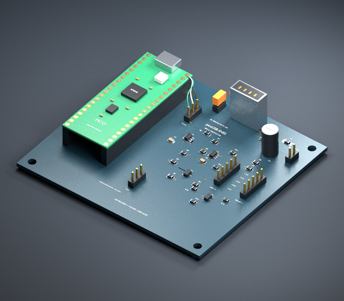
The render uses the actual PCB placements with illustrative component bodies; it is not a manufactured board or mechanical clearance certification.
CP/M-65's current SNES source still uses its original serial keyboard and floppy hardware. It needs a controller-port keyboard driver or a compatible patched ROM, and a separate mouse driver/application API for mouse use. No CP/M-65 source is silently changed by this project. Integration notes.
Use CMake, an Arm bare-metal GCC toolchain with Newlib and C++ headers, and Raspberry Pi Pico SDK 2.2.0. The application is C; the SDK also compiles its allocation hooks as C++.
git clone --branch 2.2.0 --depth 1 https://github.com/raspberrypi/pico-sdk.git ../pico-sdk
git -C ../pico-sdk submodule update --init lib/tinyusb
cmake -S . -B build-pico -DPICO_SDK_PATH="$PWD/../pico-sdk" -DPICO_BOARD=pico
cmake --build build-pico -j4
The SDK downloads/builds picotool if it is not installed; that first build needs
network access and a host C++ compiler. To use an existing installation, add
-Dpicotool_DIR=/path/to/lib/cmake/picotool. The output is
build-pico/picousb_snes.uf2; a locally built development image and checksum are
also in artifacts.
Portable tests do not need the SDK or board:
cmake -S . -B build-host -DBRIDGE_HOST_TESTS=ON
cmake --build build-host
ctest --test-dir build-host --output-on-failureRead hardware and power instructions before connecting. The Pico's USB D+/D− signals are not on its 40-pin header. Revision A needs short wires from underside test pads TP1/TP2/TP3 to carrier J4.
For flashing, disconnect external power and host devices, remove JP1, then
hold BOOTSEL while attaching the Pico micro-USB connector to the PC. Copy the
UF2 to RPI-RP2, then disconnect the PC cable. For host operation, fit JP1 and
use regulated 5 V at J2. Leave the Pico micro-USB connector empty. Connect a
suitable USB hub at J5 and connect keyboard/mouse to it. Use a self-powered hub
for the initial tests; its upstream port must not back-feed power.
J1 goes to SNES port 2 and J6 to port 1. Their five-pin carrier headers have a different numbering from the seven-position SNES connector: follow the wiring table and verify cable continuity. UART diagnostics are available at J3, 3.3 V logic, 115200 baud. The Pico LED indicates at least one selected HID device.
Protocol · Hardware · Validation · Roadmap · Credits and licenses
| Qty | Value | Footprint | References |
|---|---|---|---|
| 6 | 100 | Bridge:R_0805_2012Metric | R1, R2, R3, R8, R9, R10 |
| 6 | 100k | Bridge:R_0805_2012Metric | R5, R6, R7, R11, R12, R13 |
| 4 | M3 NPTH | MountingHole_3.2mm_M3 | H1, H2, H3, H4 |
| 2 | 100nF | Bridge:C_0805_2012Metric | C1, C3 |
| 2 | 4.7k | Bridge:R_0805_2012Metric | R4, R14 |
| 2 | BSS138 | Bridge:SOT-23 | Q1, Q2 |
| 2 | SN74LVC2G17DBVR | Bridge:SOT-23-6 | U2, U3 |
| 1 | 10uF 10V X7R | Bridge:C_0805_2012Metric | C2 |
| 1 | 150uF 10V | Bridge:CP_Radial_D6.3mm_P2.50mm | C4 |
| 1 | 500mA PTC | Bridge:Fuse_1206_3216Metric | F1 |
| 1 | 5V regulated input | Bridge:PinHeader_1x02_P2.54mm_Vertical | J2 |
| 1 | HOST POWER link | Bridge:PinHeader_1x02_P2.54mm_Vertical | JP1 |
| 1 | MOUSE / PORT 1 | Bridge:PinHeader_1x05_P2.54mm_Vertical | J6 |
| 1 | Pico USB test-pad link | Bridge:PinHeader_1x03_P2.54mm_Vertical | J4 |
| 1 | Raspberry Pi Pico (RP2040) | Bridge:Pico_Socket | U1 |
| 1 | SNES cable | Bridge:PinHeader_1x05_P2.54mm_Vertical | J1 |
| 1 | UART 3V3 | Bridge:PinHeader_1x03_P2.54mm_Vertical | J3 |
| 1 | USB-A HOST / HUB | Bridge:USB_A_Molex_105057_Vertical | J5 |
manvalan/MuonScope
Piano di rivelazione MuonScope con 16 fotodiodi VBPW34S in matrice 4×4 a passo 10 mm, per il bus MIKILAB REV5.1.


paltatech/current_sensor
Isolated delta sigma current sensor for high speed high current application

Bogdan8266/h616-board
8-layer Allwinner H616/618 SBC with DDR3, USB, Wi-Fi/BT and battery power support, designed for embedded Linux.

11philip22/tang-usb-ls-sniffer
A KiCad USB sniffer HAT for the Tang Nano 9K, designed to decode characters from compatible 1.5 Mb/s low-speed USB keyboards on the FPGA and send them over UART.


DsThakurRawat/PCB-AND-CHIP-DESIGN-WITH-AIML
All production files have been generated in manufacturing/: - Gerber Layers (RS-274X): Copper, solder masks, silkscreen, and board edge cuts (manufacturing/gerbers/) - Excellon Drill Files: Plated and non-plated drill…

ECE49022Team22/delivery-robot-pcb
Delivery robot KiCad PCB project and reusable 3.3 V LDO module
It measures 84 × 76 mm and has 2 copper layers, 1.6 mm thick.
35 parts, built around the SN74LVC2G17DBVR and BSS138. The full list of its parts is on this page, with links to each part's symbol and footprint where PCBKit's library has them.
From the salvogendut/picoUSB-SNES repository on GitHub, at the commit this page was made from: the board is hardware/picoUSB-SNES.kicad_pcb and its schematic hardware/picoUSB-SNES.kicad_sch. PCBKit opens the board in the browser, with nothing to install.
Its repository publishes it under the MIT licence: you may reuse it on that licence's terms (keep the author's notice, and for a copyleft licence share your changes alike).