2 layers39.4 × 25 mm

 saheenpalayi/SmartUPDI2
SmartUPDI is an open hardware UPDI programmer and USART adapter for modern AVR microcontrollers. It can switch between programming mode and serial communication with the target device, making it useful for both firmware…
SmartUPDI is an open-source printed circuit board by saheenpalayi, from the saheenpalayi/SmartUPDI repository on GitHub, published under the CC0-1.0 licence. It is a 2-layer board of 68.9 × 25.6 mm with 37 parts on 36 nets, routed with 295 tracks and 50 vias.
It is built around the CH340C, AP2112K-3.3 and HEF4066BT. Its parts include 8 resistors, 6 diodes, 5 capacitors, 4 connectors and 3 ICs. It belongs with the interfaces and adapters boards of this library.


SmartUPDI is an open hardware UPDI programmer and USART adapter for modern AVR microcontrollers. It can switch between programming mode and serial communication with the target device, making it useful for both firmware development and serial debugging.
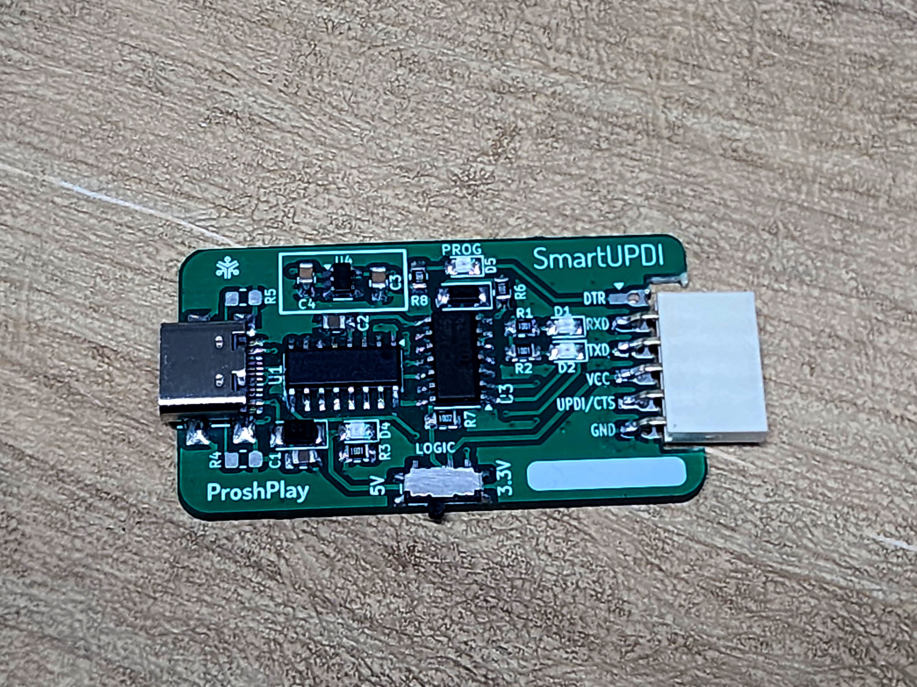
This repository contains the design files and manufacturing outputs for SmartUPDI. It includes a modified revision of the original Version 1 design. Version 1 was assembled and tested as a working prototype, and the modified revision addresses the known Version 1 issues.
The modified version in this repository improves on the original Version 1 hardware. The previously reported LED issues and macOS automatic switching issue have been resolved in this revision.
The board also provides four to five different output connector options. Users can select the connector arrangement that best suits their target hardware and solder the required connector option during assembly.
SmartUPDI has been tested with:
The original Version 1 prototype worked correctly on Linux and Windows, but had LED issues and problems with automatic switching on macOS. These issues have been addressed in the modified revision contained in this repository.
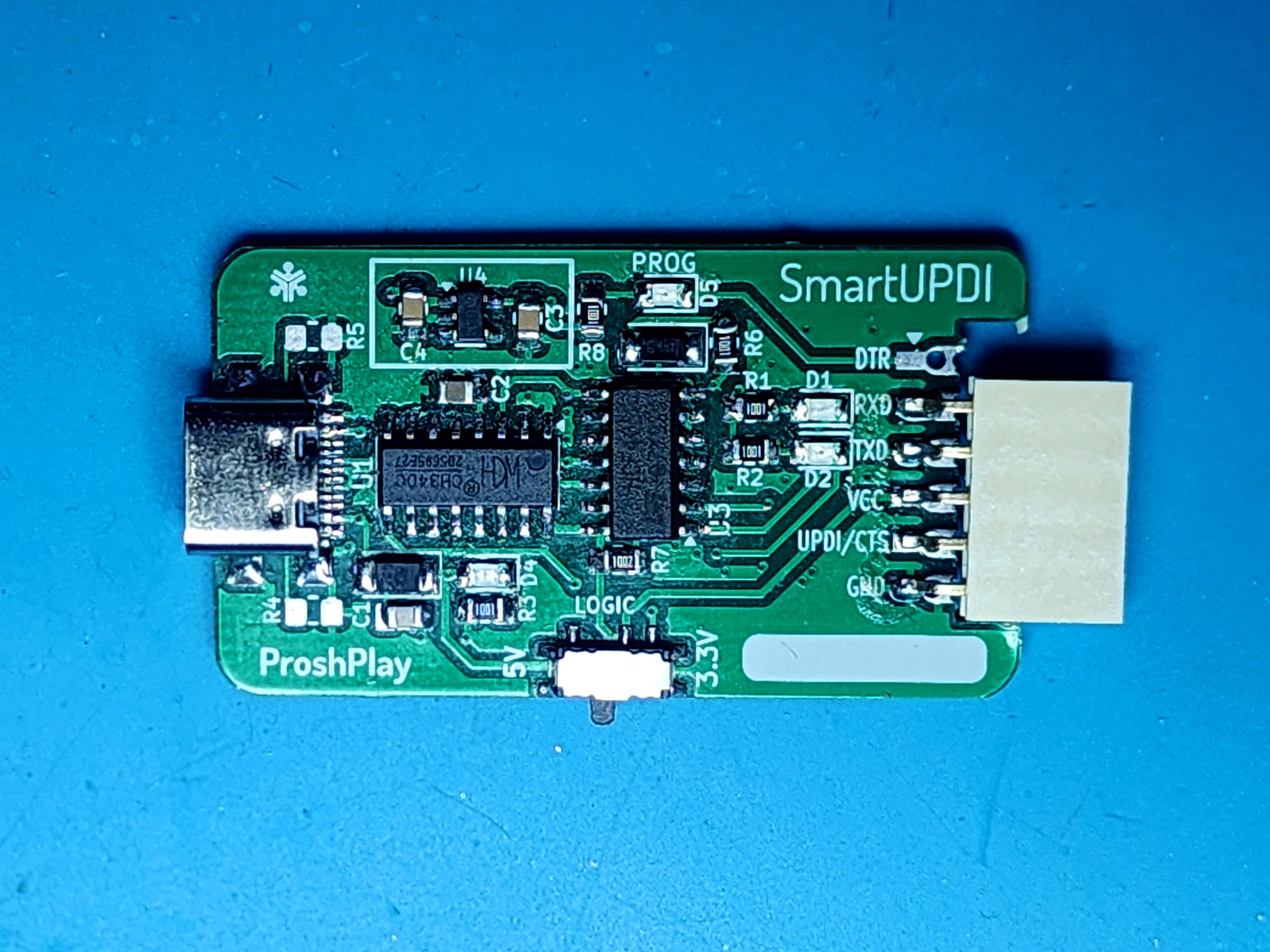
Design Files/ - KiCad project, schematic, PCB layout, and project settingsGerber Files/ - fabrication outputs for manufacturing the PCBMedia/ - project and assembled-board photographsAnyone may manufacture SmartUPDI for personal use, education, experimentation, or integration into their own projects. Review the schematic, PCB layout, and Gerber files before fabrication, and verify the board against your own target hardware and power requirements.
You may build, modify, and use SmartUPDI as needed. Reselling the SmartUPDI project, assembled boards, or kits based on this design is prohibited without the author's permission.
This project is provided as-is. Hardware assembly and use are performed at your own risk. Always confirm voltage levels, wiring, and target-device connections before programming.
See LICENSE for the license currently included with this repository. The author's intended project policy is that anyone may build and use SmartUPDI, but resale is prohibited. Because the included CC0 text permits commercial redistribution, the license file should be replaced with a license that explicitly prohibits resale if that restriction must be enforceable.
| Qty | Value | Footprint | References |
|---|---|---|---|
| 6 | , , , , , | ||
| 3 | 1k | Resistor_SMD:R_0805_2012Metric_Pad1.20x1.40mm_HandSolder | R1, R2, R8 |
| 2 | 100nF | Capacitor_SMD:C_0805_2012Metric_Pad1.18x1.45mm_HandSolder | C1, C5 |
| 2 | 1uF | Capacitor_SMD:C_0805_2012Metric_Pad1.18x1.45mm_HandSolder | C3, C4 |
| 2 | 5.1k | Resistor_SMD:R_0805_2012Metric_Pad1.20x1.40mm_HandSolder | R4, R5 |
| 2 | BLUE | LED_SMD:LED_0805_2012Metric_Pad1.15x1.40mm_HandSolder | D2, D5 |
| 2 | SW_SPDT | Button_Switch_SMD:SW_SPDT_PCM12 | SW1, SW2 |
| 2 | SolderJumper_3_Bridged12 | Jumper:SolderJumper-3_P1.3mm_Bridged12_RoundedPad1.0x1.5mm_NumberLabels | JP1, JP2 |
| 1 | 10k | Resistor_SMD:R_0805_2012Metric_Pad1.20x1.40mm_HandSolder | R7 |
| 1 | 10nF | Capacitor_SMD:C_0805_2012Metric_Pad1.18x1.45mm_HandSolder | C2 |
| 1 | 1A Schottky | PCM_fab:Diode_Schottky_MiniSMA | D3 |
| 1 | 1K | Resistor_SMD:R_0805_2012Metric_Pad1.20x1.40mm_HandSolder | R3 |
| 1 | 1N5817 / Schottky 100mA | fab:Diode_Schottky_MiniSMA | D6 |
| 1 | 1x06 Pin header 2.54 SMD | fab:PinSocket_1x06_P2.54mm_Horizontal_SMD | J2 |
| 1 | 499ohm | Resistor_SMD:R_0805_2012Metric_Pad1.20x1.40mm_HandSolder | R6 |
| 1 | 5077CR-16SMC2-BK-TR | Connector_USB:USB_C_Receptacle_G-Switch_GT-USB-7010ASV | CON1 |
| 1 | AP2112K-3.3 | Package_TO_SOT_SMD:SOT-23-5 | U4 |
| 1 | CH340C | Package_SO:SOIC-16_3.9x9.9mm_P1.27mm | U1 |
| 1 | Conn_PinHeader_FTDI_1x06_P2.54mm_Horizontal_SMD | fab:PinHeader_1x06_P2.54mm_Horizontal_SMD | J3 |
| 1 | GREEN | LED_SMD:LED_0805_2012Metric_Pad1.15x1.40mm_HandSolder | D4 |
| 1 | HEF4066BT | Package_SO:SOIC-14_3.9x8.7mm_P1.27mm | U3 |
| 1 | PinHeader_02x03_P2.54mm_Vertical_SMD | PCM_fab:PinHeader_02x03_P2.54mm_Vertical_SMD | J1 |
| 1 | RED | LED_SMD:LED_0805_2012Metric_Pad1.15x1.40mm_HandSolder | D1 |
The 36 most common of 37 parts.


jpconstantineau/NRF52-Board
This Repository is a collection of NRF5x boards.

jyancat/UART-Expansion-Card
Design files for the UART expansion card, please note this is a tested and working expansion card. Licensed under CERN-OHL-S-2.0. Uses the CH340C with switchable power and logic levels (5V and 3V3)


sparkfun/SparkFun_UM980_Triband_GNSS_RTK_Breakout
Documentation and hardware repository for the SparkFun Triband GNSS RTK Breakout, featuring the UM980 high precision GNSS/RTK module from Unicore Communications

wenzel-lab/syringe-pumps-and-controller
Design of 3d printable syringe pumps and dual controller.
It measures 68.9 × 25.6 mm and has 2 copper layers, 1.6 mm thick.
37 parts, built around the CH340C, AP2112K-3.3 and HEF4066BT. The full list of its parts is on this page, with links to each part's symbol and footprint where PCBKit's library has them.
From the saheenpalayi/SmartUPDI repository on GitHub, at the commit this page was made from: the board is Design Files/SmartUPDI.kicad_pcb and its schematic Design Files/SmartUPDI.kicad_sch. PCBKit opens the board in the browser, with nothing to install.
Its repository publishes it under the CC0-1.0 licence: you may reuse it on that licence's terms (keep the author's notice, and for a copyleft licence share your changes alike).