

2 layers82 × 100 mm
Robo car
ChefsSlaad/PCBs_and_Micropython
storing custom pcbs and micropython code for home projects
36 parts

 ryukgod26/Hermes
To use this project you just need to connect the sensors, switch and arduino nano with each other according to the wiring Diagram. Then clickConnect the Arduino nano with your computer with a USB Cable.
Hermes is an open-source printed circuit board by ryukgod26, from the ryukgod26/Hermes repository on GitHub. It is a 2-layer board of 78.6 × 59.4 mm with 5 parts on 29 nets, routed with 77 tracks and 0 vias.
It is built around the DHT11 and HC-SR04. Its parts include 1 IC and 1 switch. It belongs with the AVR (ATmega, ATtiny) boards of this library.
This is simple hermes board Created by me. It uses a Arduino Nano, 0.96 OLED Display, Ultra Sonic Sensor, DHT11 Temeperature/Humidity and a simple button. This shows the Temperature Data on the Screen First and when the Switch is pressed the data on the OLED Display get switchwd and started showing the data from the Ultra Sonic Sensor If there is a object in the range it shows how far is the object from the Ultra Sonic Sensor and if there is no object in he range then it shows "OUT OF RANGE!!".
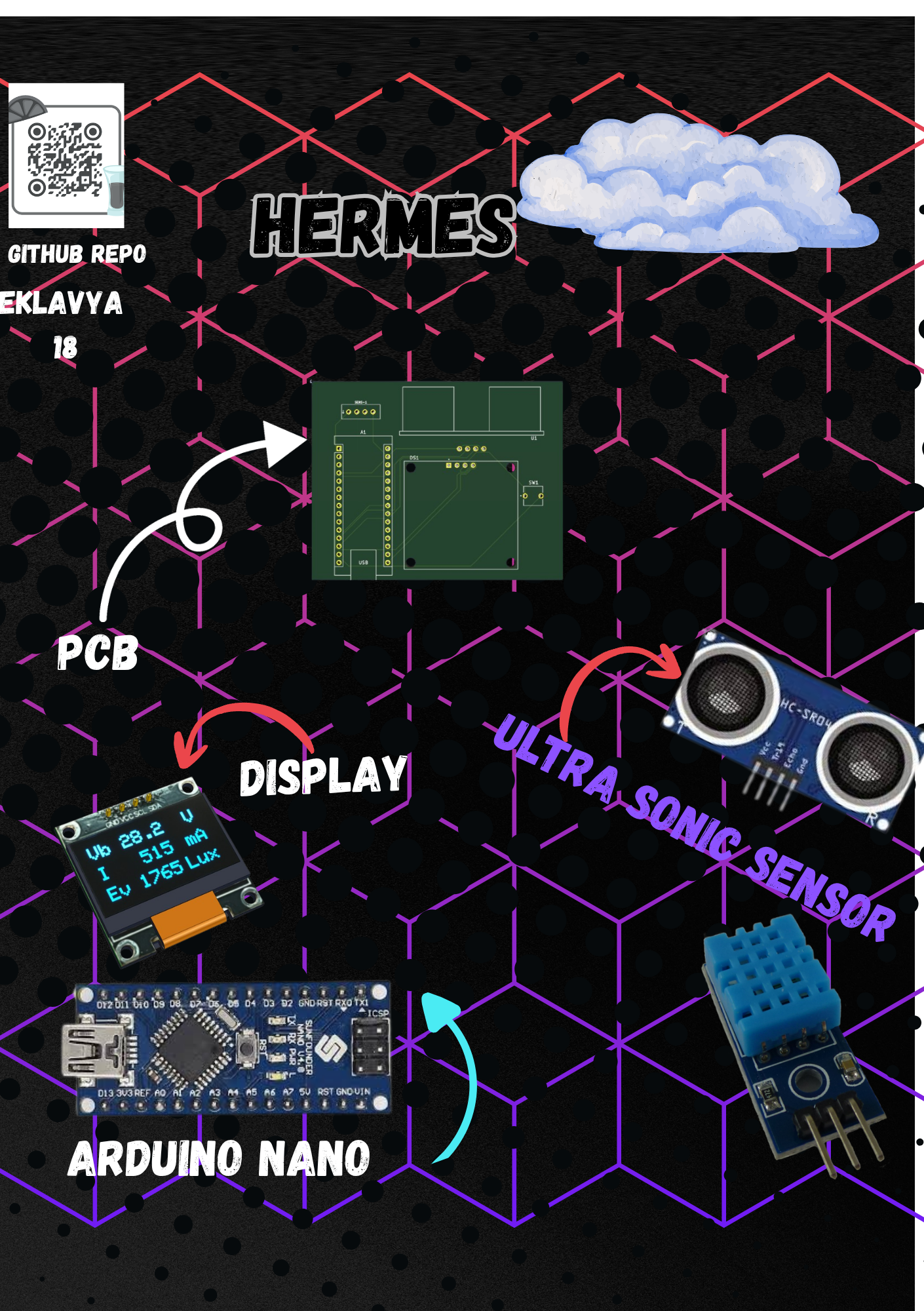
I built this Project to learn how to use Oled Display and connect different sensor with each other and know how to switch from reading data from one sensor to another. This was Learning Project built entirely to improve Hardware Skills.
To use this project you just need to connect the sensors, switch and arduino nano with each other according to the wiring Diagram. Then clickConnect the Arduino nano with your computer with a USB Cable. Then Open the arduino IDE and Select the COM port of the arduino Port. Then Upload the Code in Code/hermes_code Folder and upload that code to the arduino nano. Then It will Start Showing the Temperature of the Room to the Display and when you will press the switch then it will start reading the ultra sonic sensor and will tell the distance between the Object and the Ultra Sonic Sensor if there is a Object in range and Show that Distance in the Display.
It measures 78.6 × 59.4 mm and has 2 copper layers, 1.6 mm thick.
5 parts, built around the DHT11 and HC-SR04. The full list of its parts is on this page, with links to each part's symbol and footprint where PCBKit's library has them.
From the ryukgod26/Hermes repository on GitHub, at the commit this page was made from: the board is hardware/Hermes/Hermes.kicad_pcb and its schematic hardware/Hermes/Hermes.kicad_sch. PCBKit opens the board in the browser, with nothing to install.
Its repository states no licence, so its author keeps all rights: ask ryukgod26 before reusing the design.
ChefsSlaad/PCBs_and_Micropython
storing custom pcbs and micropython code for home projects


kennySzhucheng/EnvMonitor
🌡️ 智能环境监测站 | STM32F103C8T6 + FreeRTOS + ESP8266 | 温湿度/光照/测距/OLED菜单/ThingSpeak上云 | 从裸机到RTOS到KiCad PCB全流程


NikolaiRadke/Noko_2
The do-it-yourself Arduino-based Noko monster. Version 2 with PCB and 3D printed casing.

billtsol/Maze
This project demonstrates how to use an Arduino board, IR sensors, and a motor driver shield to create a maze-solving robot.

c-lydia/ESP-ROS2
A tiny robot with IMU (MPU5060) and an ultrasonic sensor (HC-SR04), running on micro-ROS, communicating over UDP.

dbrgn/crazyflie2-hcsr04
Ultrasonic sensor (HC-SR04) extension board for the Crazyflie 2.0