4 layers58 × 31 mm

 ryanhsiehrh/STM32WB_RF_PCB
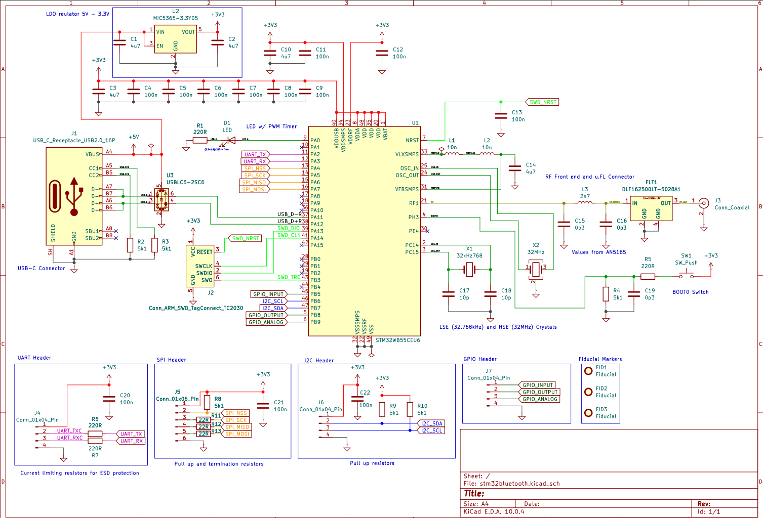
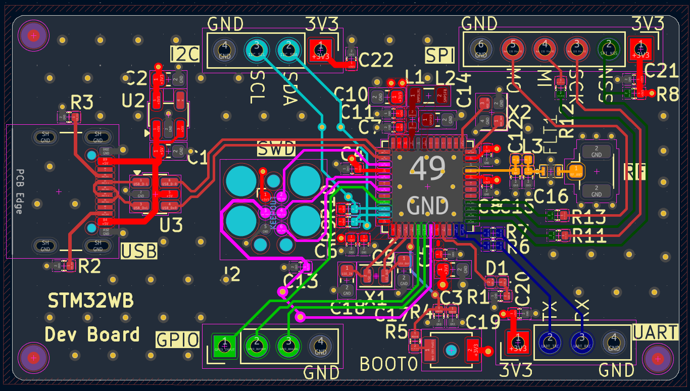
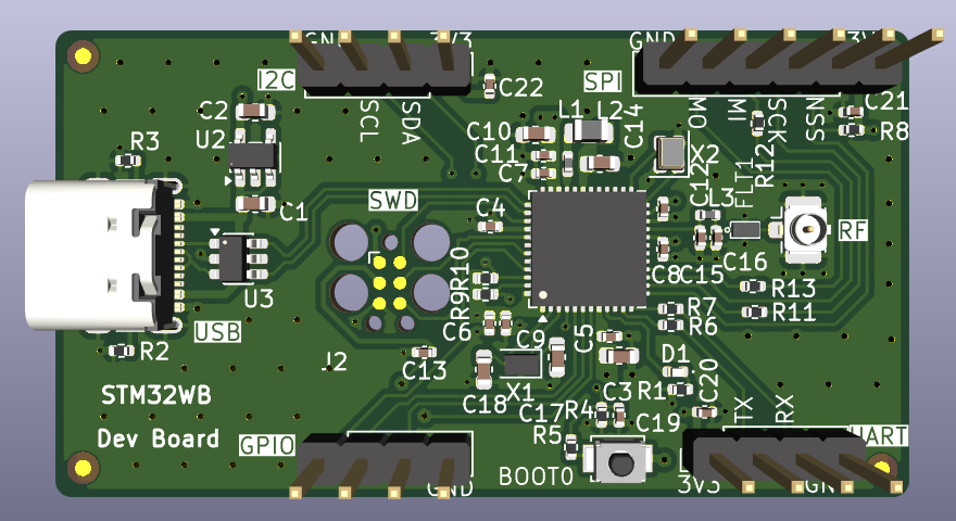
Custom 4-layer developement board centered around the STM32WB55CEU6 MCU. The board includes 2.4GHz BLE RF cicuitry, ESD protected USB, SWD, and communication interfaces: UART, I2C, SPI, GPIO
Stm32bluetooth is an open-source printed circuit board by ryanhsiehrh, from the ryanhsiehrh/STM32WB_RF_PCB repository on GitHub. It is a 4-layer board of 53 × 29 mm with 56 parts on 58 nets, routed with 375 tracks and 120 vias.
It is built around the STM32WB55CEU6, DLF162500LT-5028A1 and MIC5365-3.3YD5-TR, with the USBLC6-2SC6 among its other parts. Its parts include 22 capacitors, 13 resistors, 7 connectors, 3 ICs and 3 inductors. It belongs with the interfaces and adapters and radio and wireless boards and the STM32 boards of this library.


Custom 4-layer developement board centered around the STM32WB55CEU6 MCU. The board includes 2.4GHz BLE RF cicuitry, ESD protected USB, SWD, and communication interfaces: UART, I2C, SPI, GPIO.
Schematic:
PCB:
| Qty | Value | Footprint | References |
|---|---|---|---|
| 12 | 100n | Capacitor_SMD:C_0402_1005Metric | C4, C5, C6, C7, C8, C9, C11, C12, C13, C20, C21, C22 |
| 6 | 5k1 | Resistor_SMD:R_0402_1005Metric | R2, R3, R4, R8, R9, R10 |
| 5 | 4u7 | Capacitor_SMD:C_0603_1608Metric | C1, C2, C3, C10, C14 |
| 4 | 220R | Resistor_SMD:R_0402_1005Metric | R1, R5, R6, R7 |
| 3 | 0p3 | Capacitor_SMD:C_0402_1005Metric | C15, C16, C19 |
| 3 | 22R | Resistor_SMD:R_0402_1005Metric | R11, R12, R13 |
| 3 | Conn_01x04_Pin | Connector_PinHeader_2.54mm:PinHeader_1x04_P2.54mm_Vertical | J4, J6, J7 |
| 3 | Fiducial | Fiducial:Fiducial_1mm_Mask2mm | FID1, FID2, FID3 |
| 2 | 10p | Capacitor_SMD:C_0603_1608Metric | C17, C18 |
| 1 | 10n | Inductor_SMD:L_0402_1005Metric | L1 |
| 1 | 10u | Inductor_SMD:L_0805_2012Metric | L2 |
| 1 | 2n7 | Inductor_SMD:L_0402_1005Metric | L3 |
| 1 | 32MHz | Crystal:Crystal_SMD_2016-4Pin_2.0x1.6mm | X2 |
| 1 | 32kHz768 | Crystal:Crystal_SMD_2012-2Pin_2.0x1.2mm | X1 |
| 1 | Conn_01x06_Pin | Connector_PinHeader_2.54mm:PinHeader_1x06_P2.54mm_Vertical | J5 |
| 1 | Conn_ARM_SWD_TagConnect_TC2030 | Connector:Tag-Connect_TC2030-IDC-FP_2x03_P1.27mm_Vertical | J2 |
| 1 | Conn_Coaxial | Connector_Coaxial:U.FL_Hirose_U.FL-R-SMT-1_Vertical | J3 |
| 1 | DLF162500LT-5028A1 | 1footprintlibrary:DLF162500LT-5028A1 | FLT1 |
| 1 | LED | LED_SMD:LED_0402_1005Metric | D1 |
| 1 | MIC5365-3.3YD5 | Package_TO_SOT_SMD:TSOT-23-5 | U2 |
| 1 | STM32WB55CEU6 | Package_DFN_QFN:QFN-48-1EP_7x7mm_P0.5mm_EP5.6x5.6mm | U1 |
| 1 | SW_Push | Button_Switch_SMD:SW_SPST_B3U-1000P-B | SW1 |
| 1 | USBLC6-2SC6 | Package_TO_SOT_SMD:SOT-23-6 | U3 |
| 1 | USB_C_Receptacle_USB2.0_16P | Connector_USB:USB_C_Receptacle_GCT_USB4105-xx-A_16P_TopMnt_Horizontal | J1 |


OdaiJ/stm32-bt-board
My attempt at following the Phil's Lab KiCad V7 tutorial on YouTube

shivamtiwari020505/stm32wb55-ble-dev-board
Custom STM32WB55 development board integrating 2.4GHz BLE 5.x, LPUART, I2C, and UART via RS232/DB9 for PC and industrial machine interfacing. Designed to bridge modern wireless IoT with legacy wired systems.


justinfederico/STM32testPCB
Custom STM32WB microcontroller to practice my PCB schematic and layout skills. Looking to get it printed soon! Bear in mind that this is an ameuter project, so there will probably be errors aplenty.
It measures 53 × 29 mm and has 4 copper layers, 1.6 mm thick.
56 parts, built around the STM32WB55CEU6, DLF162500LT-5028A1, MIC5365-3.3YD5-TR and USBLC6-2SC6. The full list of its parts is on this page, with links to each part's symbol and footprint where PCBKit's library has them.
From the ryanhsiehrh/STM32WB_RF_PCB repository on GitHub, at the commit this page was made from: the board is KiCad Files/stm32bluetooth.kicad_pcb and its schematic KiCad Files/stm32bluetooth.kicad_sch. PCBKit opens the board in the browser, with nothing to install.
Its repository states no licence, so its author keeps all rights: ask ryanhsiehrh before reusing the design.