
2 layers103.8 × 50 mm
Galagino pcb set
harbaum/galagino
A Galaga, Pac-Man and Donkey Kong arcade emulator for the ESP32
26 parts558

 rutubetsiz/uyanik
Remote PC Power Control
Uyanik is an open-source printed circuit board by rutubetsiz, from the rutubetsiz/uyanik repository on GitHub, published under the GPL-3.0 licence. It is a 2-layer board of 65 × 50 mm with 23 parts on 46 nets, routed with 107 tracks and 0 vias.
It is built around the ESP32-DEVKITC-VE. Its parts include 8 connectors, 4 ICs, 3 resistors, 3 switches and 1 diode. It belongs with the home automation and IoT and computers and single-board computers boards and the ESP32 boards of this library.
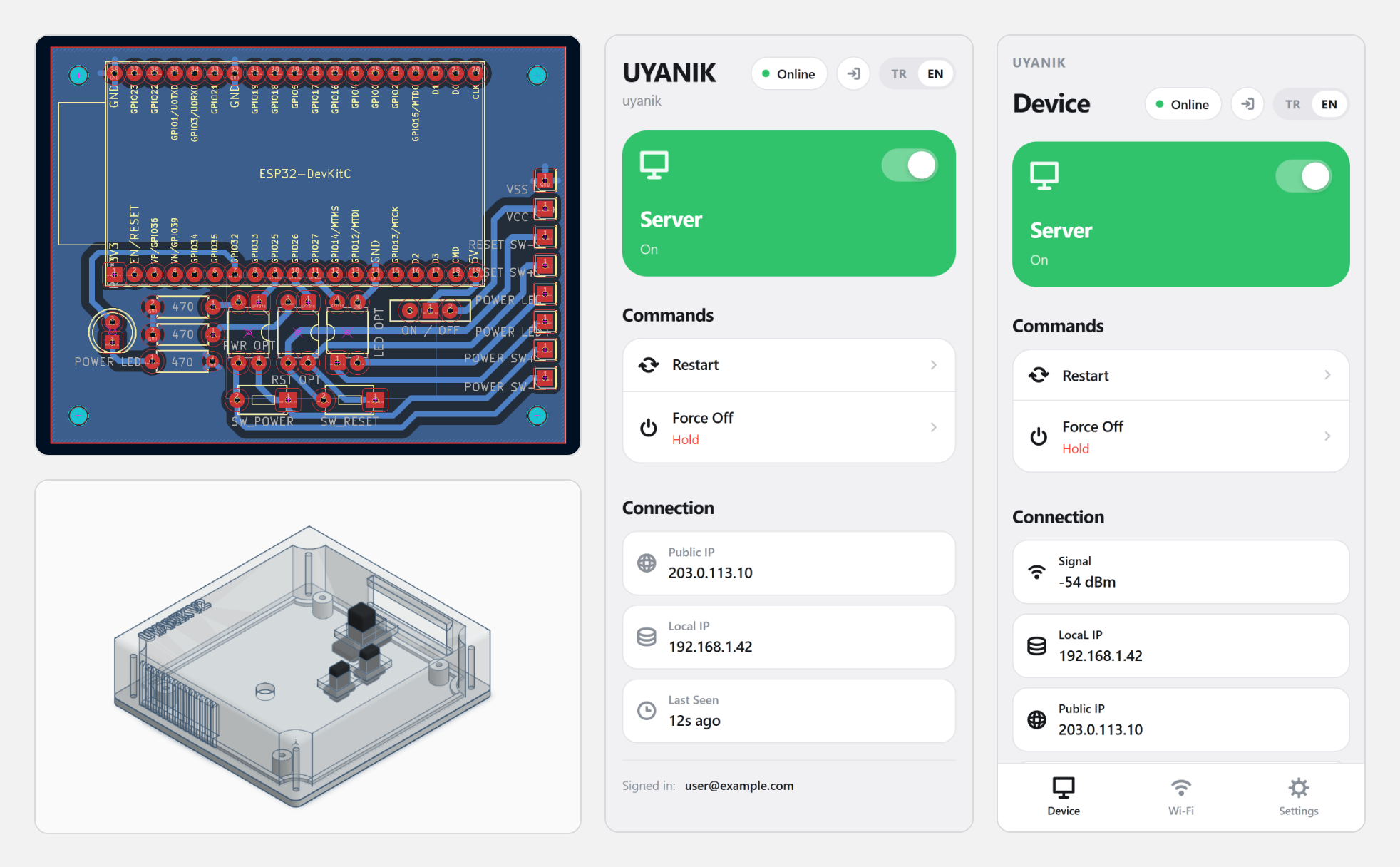
A device for turning a remote computer on and off. As long as you have internet access, it doesn’t matter where in the world you are.
It started as a summer project. I had turned a spare computer into a server, but I didn’t want to leave it running all the time. University was about to start, and I needed a way to turn it on and off remotely. Shutting down a remote machine is easy, turning it on is not. Wake-on-LAN isn’t enough, and if you’re behind CGNAT on top of that... The answer to all of it was a device that stays on at home, so I built one. Wherever I am, UYANIK lets me open a web panel and turn my server on and off as if I were at home pressing the button on the case.
The device connects to the motherboard’s front panel header (JFP1). When a command comes in, the optocoupler switches and the motherboard sees it as a button press. By reading the power LED line on the same header, it also knows whether the computer is on or off.
Since the device takes up the header, the case’s front panel is left out; there’s nowhere to plug in the case’s power button, reset button and LED. That’s why the device has its own power and reset buttons, plus an LED that shows whether the computer is on. So you don’t lose the case button, it just moves onto the device.
Commands go through Firebase Realtime Database. When you send a command from the panel, it’s written to a field in the database; the device polls that field and runs the command when it sees it. Status comes back the same way in the other direction.
The reason for Firebase is that the device and the phone are on different networks, usually behind CGNAT. A direct connection isn’t possible, so a meeting point is needed. No port forwarding, DDNS or static IP required.
Besides the remote panel there’s also a local panel. It lives in the device’s own flash and works without internet. If you’re on the same network, you can connect to the device directly and send commands. When the device can’t connect to any network, it opens its own hotspot and the same panel shows up as the setup screen.
The device has to keep running while the computer is off, after all it’s the thing that turns the machine on. I power it from the motherboard’s USB header, JUSB2. While the computer is off, the power on that header actually comes from the power supply’s standby line, which stays live as long as the plug is in. The motherboard doesn’t feed it to the header by default, so two BIOS settings need to be changed. Details are below under Power.
GPIO25 drives the power button’s optocoupler, GPIO26 the reset button’s. GPIO27 reads the signal coming from the power LED’s optocoupler.
GPIO4 is reserved for factory reset. There’s no button for it on the board; to reset, short this pin to GND and hold it for five seconds without interruption.
GPIO32 was added in version 2. It drives an LED output that shows the computer is on.
To connect to JFP1, female front panel cables are enough if you can find them. Otherwise you can modify female-to-female jumper wires.
I tried, as much as I could, to make this work on motherboards from different manufacturers, not just one. An optocoupler wasn’t strictly necessary; the buttons could have been driven with transistors and the power LED read directly through resistors. I chose the optocoupler because it doesn’t require making assumptions about the motherboard’s internal circuitry. The buttons’ pull-up voltage or which side the LED is driven from can vary from board to board, while an optocoupler works the same way on all of them. Since the cost difference is tiny, I went with the solution that isn’t affected by differences between boards.
The device needs to stay up while the computer is off. There are a few ways to do this.
One is from the motherboard, through the JUSB headers. This is how I did it. But there’s a catch: with default settings, the motherboard doesn’t supply standby power to the USB headers while it’s off. You need to change BIOS settings. The first is EuP 2013 or ErP Ready (the name depends on your board); on MSI it’s under Advanced, in the Power Management Setup menu. Set it to Disabled. The second is Resume By USB Device, also under Advanced but in the Wake Up Event Setup menu. Set it to Enabled. Measure between the header’s VCC and GND pins, you should see around 5 V. If you don’t, try the other header; some motherboards only supply standby power to certain ports. The downside: when the power goes out or the motherboard loses power, the device can’t get power until the computer is started by hand.
Another is directly from the power supply, pin 9 of the 24-pin connector. The purple wire. It’s completely independent of the BIOS because you’re taking power before the motherboard distributes it; no setting can turn it off. In return, you need a breakout board or a tap connector in between. If you don’t want to mess with the BIOS, or your motherboard never gives standby power to the headers, this way will definitely work.
A third option is to power the device directly from a battery or an adapter. The current design isn’t set up for that, so it would need modification.
hardware/ contains the KiCad project and PDF exports.
I made the PCB myself, so I designed it to suit home etching. You can make it yourself, or open the KiCad project, change it to your liking and send it off to be manufactured. None of this is required, the circuit works on a breadboard too.
case/ contains the model.
You can 3D print it. All the parts are in one file, so you may need to separate them.
It builds with the Arduino IDE. The folder name has to match the .ino file, so open the software/UYANIK/ folder as it is.
If you edit panel.html, you need to regenerate the copy that gets embedded in the device:
python build_html.pyTo check whether the two match:
python build_html.py --kontrolOn first boot the device prints three values to the serial port: the hotspot network name, the panel password and the OTA password.
SSID : UYANIK-XXXX
Password : ...
OTA : ...
Save these somewhere. They don’t change on factory reset. If you change the panel password later, the value here stops working, but a factory reset brings it back.
If no network is saved, the device opens its own hotspot. Once your phone is connected, go to uyanik.local to open the panel; if that doesn’t work, use 192.168.4.1.
After it joins a network, you can reach the device at uyanik.local or at the local IP shown in the panel. The hotspot stays up for another 25 seconds so you can see the new address.
Everyone sets up their own Firebase project.
Create a new project in the Firebase console and add a Realtime Database to it. In the Authentication section, enable the Email/Password provider and create an account for the device.
Finally, lock the database rules to that account’s UID:
{
  "rules": {
      ".read":  "auth != null && auth.uid === 'UID'",
      ".write": "auth != null && auth.uid === 'UID'"
  }
}
Once that’s done, enter the following in the Settings tab of the device’s panel: the Realtime Database URL, the Web API Key, the email and password of the account you created, and a device name.
software/web/public/index.html is a single static page and can be used in two ways.
To deploy it to Firebase Hosting, from the software/web/ folder:
firebase use --addfirebase deploy --only hostingSince it’s a static file, you can also host it on your own server.
You can also open it directly via file://.
When the panel first opens, it asks for the database URL, the Web API Key and the device name. These are only stored in the browser and are never sent anywhere.
Short GPIO 4 to GND and hold it for five seconds without interruption. A single break resets the counter.
A reset erases the Wi-Fi network and its password, the Firebase settings, the device and hotspot names, and the panel password if you changed it. It does not touch the panel and OTA passwords generated on first boot.
GPL-3.0. See LICENSE for details.
| Qty | Value | Footprint | References |
|---|---|---|---|
| 3 | 470 | Resistor_THT:R_Axial_DIN0207_L6.3mm_D2.5mm_P7.62mm_Horizontal | R1, R2, R3 |
| 1 | ESP32-DevKitC | PCM_Espressif:ESP32-DevKitC | U3 |
| 1 | LED OPT | Package_DIP:DIP-4_W7.62mm | U5 |
| 1 | ON / OFF | Button_Switch_THT:SW_Slide-03_Wuerth-WS-SLTV_10x2.5x6.4_P2.54mm | SW3 |
| 1 | POWER LED | LED_THT:LED_D5.0mm | D1 |
| 1 | POWER LED+ | Connector_PinHeader_2.54mm:PinHeader_1x01_P2.54mm_Vertical | J5 |
| 1 | POWER LED- | Connector_PinHeader_2.54mm:PinHeader_1x01_P2.54mm_Vertical | J6 |
| 1 | POWER SW+ | Connector_PinHeader_2.54mm:PinHeader_1x01_P2.54mm_Vertical | J1 |
| 1 | POWER SW- | Connector_PinHeader_2.54mm:PinHeader_1x01_P2.54mm_Vertical | J2 |
| 1 | PWR OPT | Package_DIP:DIP-4_W7.62mm | U4 |
| 1 | RESET SW+ | Connector_PinHeader_2.54mm:PinHeader_1x01_P2.54mm_Vertical | J3 |
| 1 | RESET SW- | Connector_PinHeader_2.54mm:PinHeader_1x01_P2.54mm_Vertical | J4 |
| 1 | RST OPT | Package_DIP:DIP-4_W7.62mm | U2 |
| 1 | SW_POWER | Button_Switch_THT:SW_PUSH_1P1T_6x3.5mm_H4.3_APEM_MJTP1243 | SW2 |
| 1 | SW_RESET | Button_Switch_THT:SW_PUSH_1P1T_6x3.5mm_H4.3_APEM_MJTP1243 | SW1 |
| 1 | VCC | Connector_PinHeader_2.54mm:PinHeader_1x01_P2.54mm_Vertical | J14 |
| 1 | VSS | Connector_PinHeader_2.54mm:PinHeader_1x01_P2.54mm_Vertical | J13 |
The 19 most common of 23 parts.
harbaum/galagino
A Galaga, Pac-Man and Donkey Kong arcade emulator for the ESP32

RParkerE/OpenSilicon
OpenSilicon enables DIY semiconductor fabrication with open-source guides for building IC equipment at home. The project includes BOMs, 3D files, firmware, and PDKs, supporting makers and researchers in chip fabrication.

cole8888/SRNE-Solar-Charge-Controller-Monitor
Read data from SRNE solar charge controllers.


ste2425/PSP-Bluetooth-AVConnector
An AV-Out Breakout library for the PSP. Providing Kicad symbols and footprints to interface with the PSP 2/3K AVOut socket (also known as the TVOut socket)

It measures 65 × 50 mm and has 2 copper layers, 1.6 mm thick.
23 parts, built around the ESP32-DEVKITC-VE. The full list of its parts is on this page, with links to each part's symbol and footprint where PCBKit's library has them.
From the rutubetsiz/uyanik repository on GitHub, at the commit this page was made from: the board is hardware/UYANIK.kicad_pcb and its schematic hardware/UYANIK.kicad_sch. PCBKit opens the board in the browser, with nothing to install.
Its repository publishes it under the GPL-3.0 licence: you may reuse it on that licence's terms (keep the author's notice, and for a copyleft licence share your changes alike).