
2 layers100 × 100 mm
Pico breadboard
rustemsevik/pico-Breadboard-Kit
This is a Raspberry Pi Pico breadboard kit designed for students to learn and experiment with basic electronics and microcontroller programming.
48 parts1MIT

 rustemsevik/pico-Breadboard-Kit1
This is a Raspberry Pi Pico breadboard kit designed for students to learn and experiment with basic electronics and microcontroller programming.
Pico breadboard is an open-source printed circuit board by rustemsevik, from the rustemsevik/pico-Breadboard-Kit repository on GitHub, published under the MIT licence. It is a 2-layer board of 100 × 93 mm with 24 parts on 39 nets, routed with 151 tracks and 0 vias.
It is built around the BC517. Its parts include 6 connectors, 5 resistors, 4 diodes and 2 ICs. It belongs with the RP2040 boards of this library.
This is a Raspberry Pi Pico breadboard kit designed for students to learn and experiment with basic electronics and microcontroller programming.
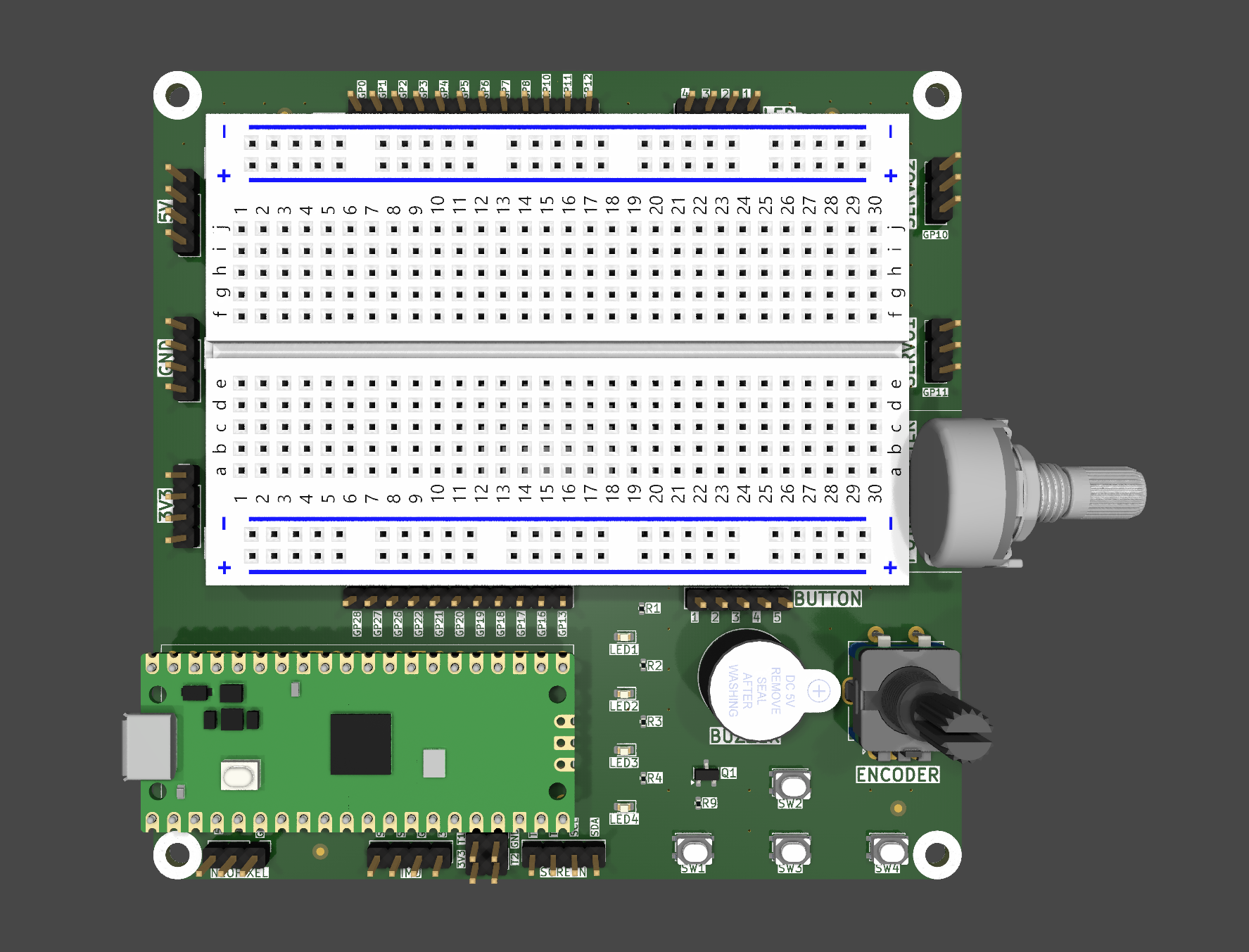
See the included v2/pico-breadboard.pdf for the detailed wiring.
This kit is ideal for beginner to intermediate-level microcontroller projects, robotics experiments, and educational settings.
| Qty | Value | Footprint | References |
|---|---|---|---|
| 4 | LED | Library:LED_D5.0mm | LED1, LED2, LED3, LED4 |
| 4 | R_US | Library:R_Axial_DIN0204_L3.6mm_D1.6mm_P7.62mm_Horizontal | R1, R2, R3, R4 |
| 3 | LOGO | Library:LOGO | G***, G***, G*** |
| 2 | Conn_01x20 | Library:PinHeader_1x20_P2.54mm_Vertical | J6, J7 |
| 2 | SW_SPST | Library:SW_PUSH_6mm | BUTTON1, BUTTON2 |
| 1 | 1K | Library:R_Axial_DIN0204_L3.6mm_D1.6mm_P7.62mm_Horizontal | R9 |
| 1 | 3.3V CONNECTOR | Library:PinHeader_1x04_P2.54mm_Vertical | J5 |
| 1 | 5V CONNECTOR | Library:PinHeader_1x04_P2.54mm_Vertical | J3 |
| 1 | BC517 | Library:TO-92_Inline | TR1 |
| 1 | Buzzer | Library:Buzzer_15x7.5RM7.6 | BZ1 |
| 1 | GND CONNECTOR | Library:PinHeader_1x04_P2.54mm_Vertical | J4 |
| 1 | Pico | Library:RPi_Pico_SMD_TH | U1 |
| 1 | SCREEN CONNECTOR | Library:PinHeader_1x04_P2.54mm_Vertical | J8 |
| 1 | ~ | Library:Breadboard | U2 |
rustemsevik/pico-Breadboard-Kit
This is a Raspberry Pi Pico breadboard kit designed for students to learn and experiment with basic electronics and microcontroller programming.


altLab/AltoEspectro
Projecto de Uma Camara de CCD arrefecida para Espectroscopia, imagem de scanning, ou para fotografia panorâmica se utilizada com cabeça panorâmica.


frubem/NE_Delta_Schematics
Forked from https://codeberg.org/hkzlab/NE_Delta_Schematics


liveboxandy/ZX-Spider-48
ZX Spider 48K by 'Skoti' https://github.com/konkotgit/ZX-48-Spider recreated in Kicad 10 to get a full ibom including tracks and vias. The gerbers in the Gerbers folder are those from Skoti.
It measures 100 × 93 mm and has 2 copper layers, 1.6 mm thick.
24 parts, built around the BC517. The full list of its parts is on this page, with links to each part's symbol and footprint where PCBKit's library has them.
From the rustemsevik/pico-Breadboard-Kit repository on GitHub, at the commit this page was made from: the board is v1/hardware/pico-breadboard.kicad_pcb and its schematic v1/hardware/pico-breadboard.kicad_sch. PCBKit opens the board in the browser, with nothing to install.
Its repository publishes it under the MIT licence: you may reuse it on that licence's terms (keep the author's notice, and for a copyleft licence share your changes alike).