2 layers68.5 × 53.5 mm
Steering wheel TX
repmanga/steering_wheel
This is PCB file of multisteering wheel for ECUmaster EMU black ECU
128 parts1MIT

 rupantar2002/featherbyte-uno1
Arduino Uno footprint, RISC-V heart. Built on the WCH CH32V203C8T6
Featherbyte uno v1.0.0 is an open-source printed circuit board by rupantar2002, from the rupantar2002/featherbyte-uno repository on GitHub, published under the MIT licence. It is a 2-layer board of 54 × 60 mm with 65 parts on 70 nets, routed with 827 tracks and 304 vias.
It is built around the USBLC6-2P6, AMS1117-3.3 and TJA1050, with the JUMPER2 among its other parts. Its parts include 17 capacitors, 14 resistors, 9 connectors, 5 ICs and 4 diodes. It belongs with the RISC-V boards of this library.



A RISC-V development board in the Arduino Uno footprint.
USB-C • Arduino-compatible headers • CAN • Open hardware
Hardware · References · Getting started · Manufacturing · Project status
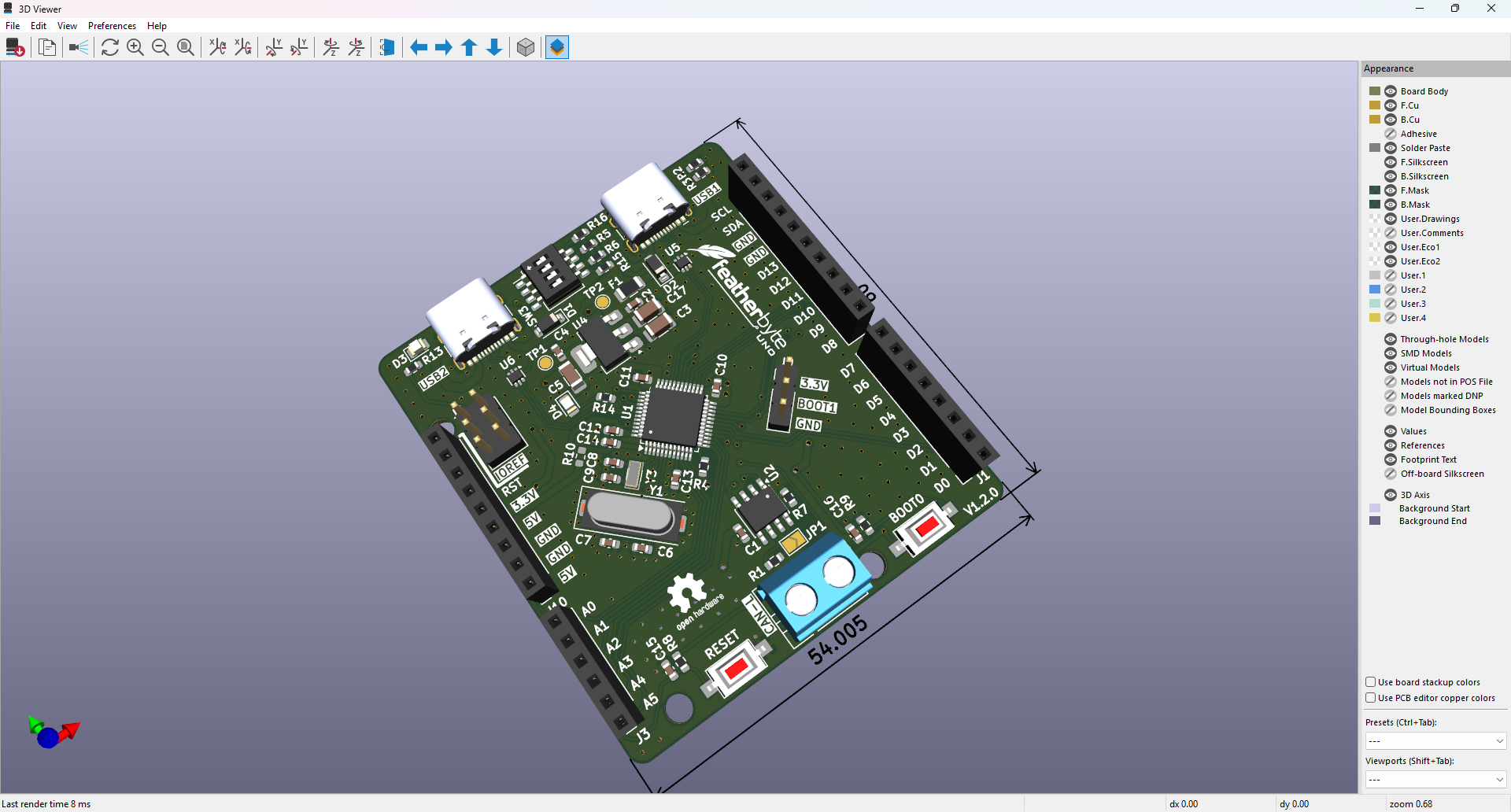
Featherbyte Uno brings the WCH CH32V203 RISC-V microcontroller to the familiar Arduino Uno form factor. It is designed for projects that want the practical shield ecosystem, generous headers, modern USB-C connectivity, and a hardware CAN interface in one open, inspectable board design.
[!WARNING] This is an active hardware project, not yet a production-qualified board. Review the design files and validate the board for your use case before ordering or deploying hardware.
| Featherbyte Uno provides | |
|---|---|
| Compute | WCH CH32V203CxT6, a 32-bit RISC-V MCU based on WCH's QingKe V4B core |
| Form factor | Arduino Uno–compatible header layout, board outline, and mounting pattern |
| USB | Two USB-C receptacles: a USB device/power-input connection and a USB host + device/power-input connection |
| Field bus | On-board TJA1050 high-speed CAN transceiver with a screw terminal for CANH/CANL |
| Debug | Dedicated SWD programming/debug header |
| Boot control | BOOT0 push button and BOOT1 selection jumper |
| Power & protection | 5 V and 3.3 V header rails, USB protection, and labelled power connections |
| Design source | Native KiCad schematic, PCB, symbols, footprints, 3D models, and Gerbers |
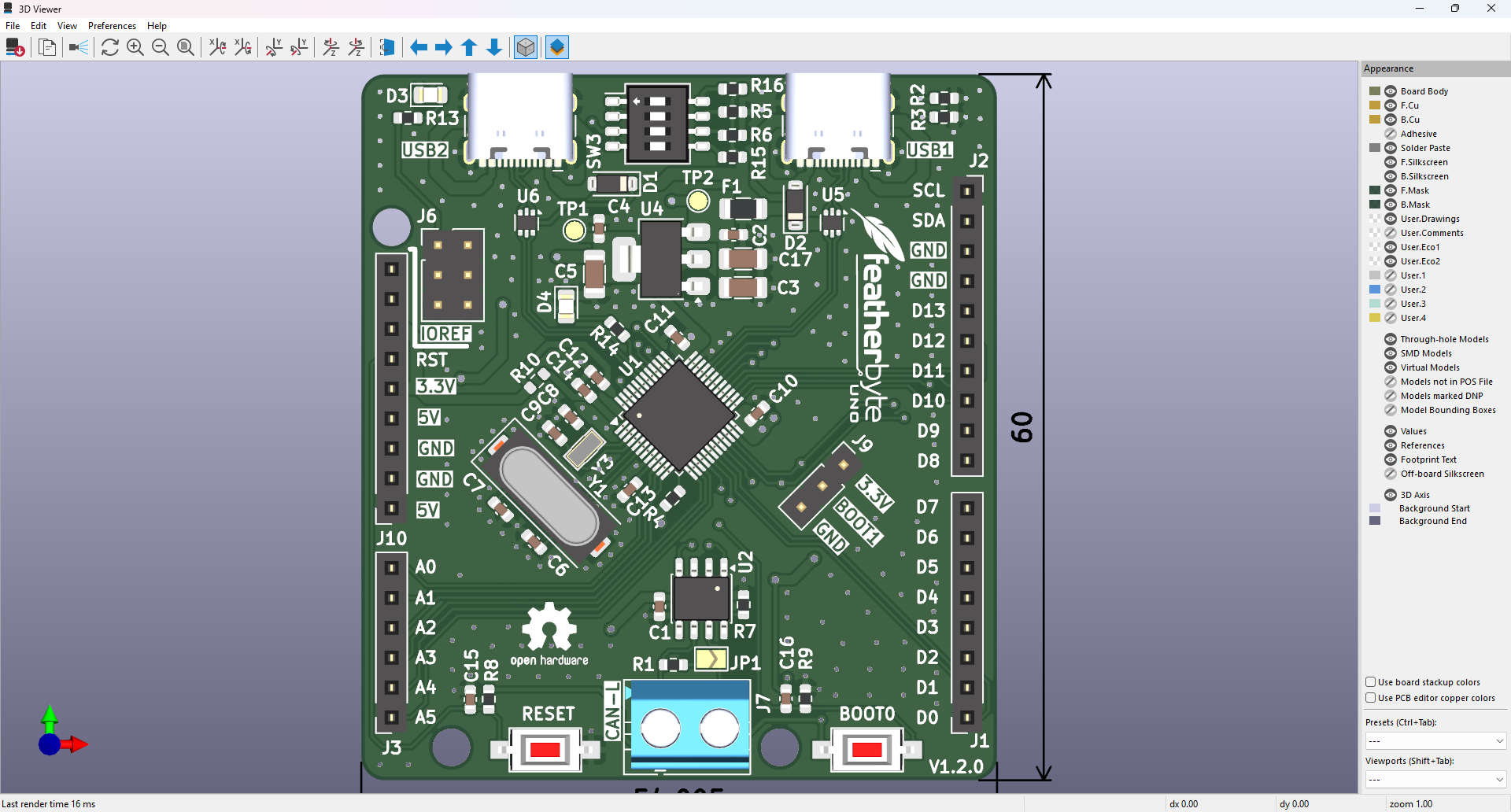
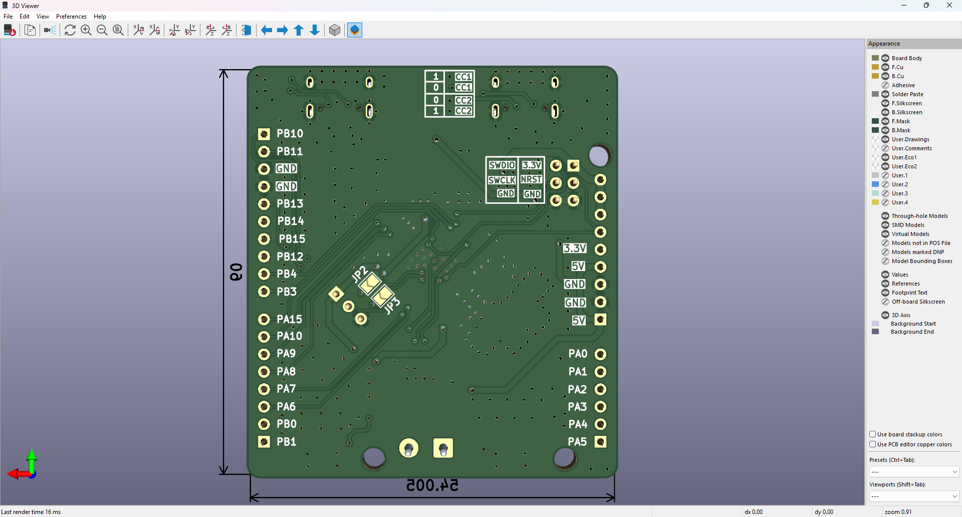
The board preserves the recognizable Uno layout while exposing CH32V203 GPIO on the standard-style digital and analog header positions. The front side carries both USB-C connections, the MCU, boot/reset controls, CAN terminal, and the Arduino-compatible headers. The reverse side provides a clearly labelled SWD header and additional breakout access.
| Interface | What it is for |
|---|---|
| USB1 / USB-C device | Device-mode connection and power input |
| USB2 / USB-C host + device | USB host/device connection and power input |
| CAN | High-speed CAN through the TJA1050 transceiver and CANH/CANL terminal |
| SWD | SWDIO, SWCLK, NRST, 3.3 V, and GND for programming and debugging |
| Arduino headers | Digital, analog, power, I²C, and SPI-style expansion in the Uno form factor |
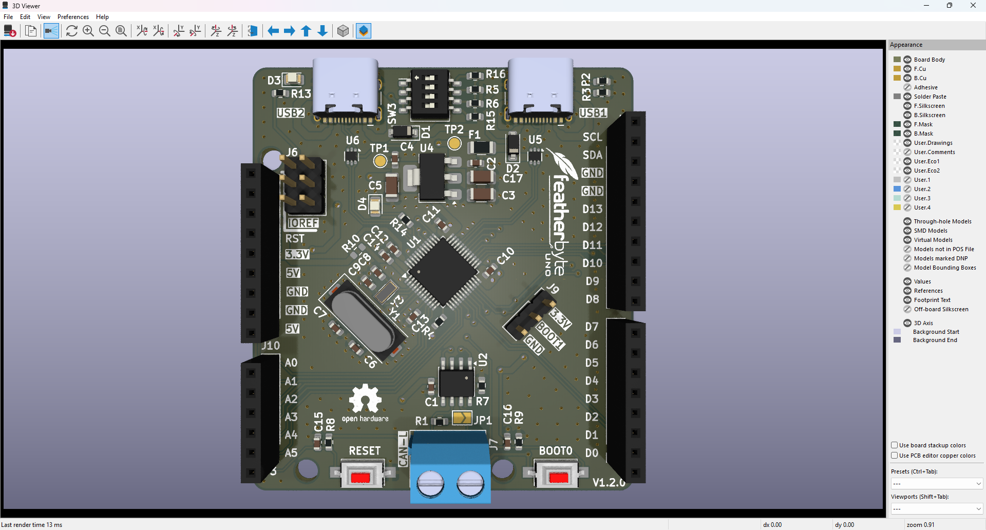
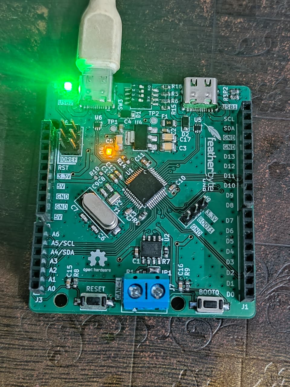
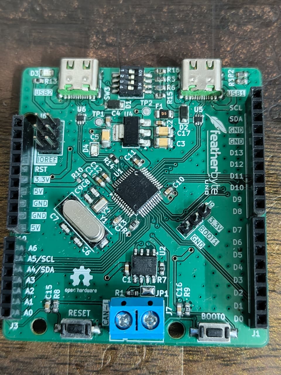
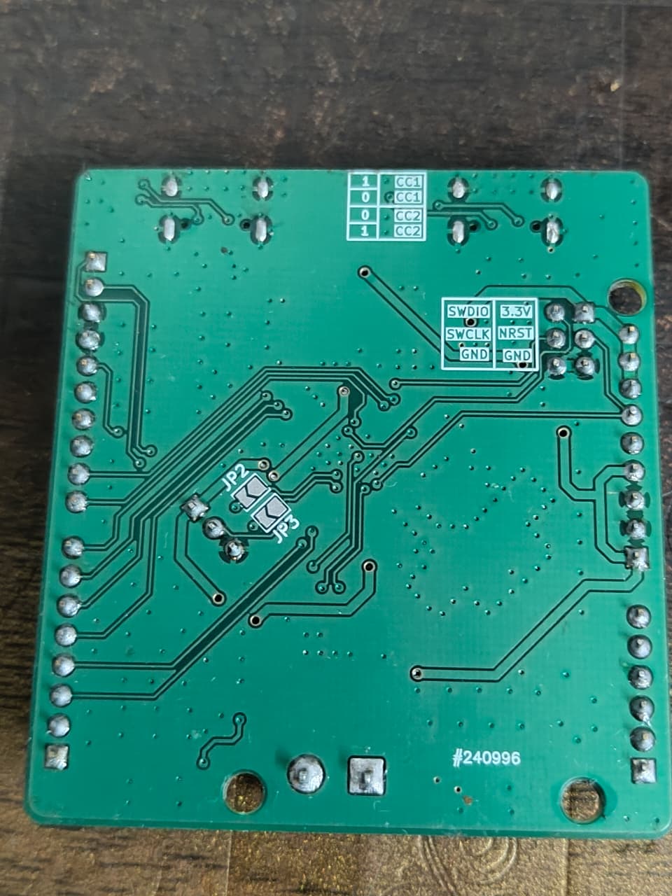
The images above show an assembled Featherbyte Uno prototype on the bench.
[!CAUTION] These photographs show an early board revision. The current KiCad project includes silkscreen corrections and additions that are not reflected on this prototype. Treat the checked-in design files as the source of truth for the current revision.
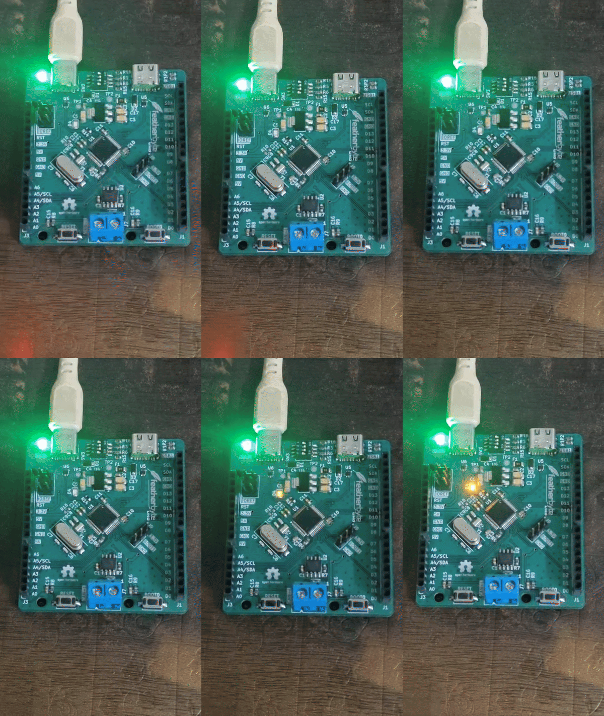
A blink test running on the assembled prototype. This demonstrates basic firmware execution on real hardware; it does not constitute full board validation.
.
├── hardware/
│   └── featherbyte-uno-v1.0.0/
│       ├── featherbyte-uno-v1.0.0.kicad_pro  # KiCad project
│       ├── featherbyte-uno-v1.0.0.kicad_sch  # schematic
│       ├── featherbyte-uno-v1.0.0.kicad_pcb  # PCB layout
│       ├── Gerber/                           # fabrication outputs
│       ├── 3d/                               # component STEP models
│       ├── footprints/                       # custom footprints
│       └── sym/                              # project symbol libraries
├── docs/                                     # schematic and component references
└── images/ # board renders used hereThe documents below are checked into the repository for offline design review and bring-up.
| Document | Purpose |
|---|---|
| Featherbyte Uno schematics v1.2.0 | Current schematic reference export |
| CH32V203 datasheet | MCU electrical characteristics, pin functions, and package details |
| CH32FV2x / V3x reference manual | MCU peripherals, registers, and programming reference |
| QingKe V4 processor manual | RISC-V core architecture and instruction-set reference |
| TJA1050 datasheet | High-speed CAN transceiver reference |
hardware/featherbyte-uno-v1.0.0/featherbyte-uno-v1.0.0.kicad_pro in KiCad.The board exposes an SWD header labelled SWDIO, SWCLK, NRST, 3.3V, and GND. Connect a compatible 3.3 V SWD debugger to this header. Firmware, toolchain, bootloader, and flashing instructions are not yet included in this repository—please treat bring-up as development work until those are published.
Ready-to-export fabrication files are in hardware/featherbyte-uno-v1.0.0/Gerber. Before submitting an order:
The included hardware project identifies the current schematic revision as v1.2.0. The directory name is retained as featherbyte-uno-v1.0.0 to match the checked-in project and fabrication paths.
| Area | Status |
|---|---|
| KiCad source | Available |
| Gerber fabrication outputs | Available |
| PCB renders | Available |
| Firmware and examples | Not yet published here |
| BOM / assembly documentation | Not yet published here |
| License | MIT License |
Design review, testing notes, issues, and pull requests are welcome. For hardware changes, please include the relevant KiCad source changes and describe any electrical, mechanical, or manufacturing impact.
| Qty | Value | Footprint | References |
|---|---|---|---|
| 10 | 100n | Capacitor_SMD:C_0603_1608Metric | C1, C2, C4, C10, C11, C12, C13, C14, C15, C16 |
| 5 | 0R | Resistor_SMD:R_0603_1608Metric | R4, R7, R10, R15, R16 |
| 4 | 5K1 | Resistor_SMD:R_0603_1608Metric | R2, R3, R5, R6 |
| 3 | 10u | Capacitor_SMD:C_1206_3216Metric | C3, C5, C17 |
| 2 | 10K | Resistor_SMD:R_0603_1608Metric | R8, R9 |
| 2 | 12pF | Capacitor_SMD:C_0603_1608Metric | C8, C9 |
| 2 | 1K | Resistor_SMD:R_0603_1608Metric | R13, R14 |
| 2 | 1N5819 | Diode_SMD:D_SOD-123 | D1, D2 |
| 2 | 22pF | Capacitor_SMD:C_0603_1608Metric | C6, C7 |
| 2 | Jumper | Jumper:SolderJumper-2_P1.3mm_Open_TrianglePad1.0x1.5mm | JP1, JP2 |
| 2 | USBLC6-2P6 | Package_TO_SOT_SMD:SOT-666 | U5, U6 |
| 2 | USB_C_Receptacle_16P | Connector_USB:USB_C_Receptacle_HCTL_HC-TYPE-C-16P-01A | J5, J8 |
| 1 | 120R | Resistor_SMD:R_0603_1608Metric | R1 |
| 1 | 32.768K | Crystal:Crystal_SMD_3215-2Pin_3.2x1.5mm | Y3 |
| 1 | 3V3 | TestPoint:TestPoint_Pad_D1.5mm | TP1 |
| 1 | 500mA | Fuse:Fuse_1206_3216Metric | F1 |
| 1 | 5V | TestPoint:TestPoint_Pad_D1.5mm | TP2 |
| 1 | 8M | Crystal:Crystal_SMD_HC49-SD | Y1 |
| 1 | AMS1117-3.3 | Package_TO_SOT_SMD:SOT-223-3_TabPin2 | U4 |
| 1 | BOOT0 | Button_Switch_SMD:SW_SPST_CK_RS282G05A3 | SW2 |
| 1 | BOOT1 | Connector_PinHeader_2.54mm:PinHeader_1x03_P2.54mm_Vertical | J9 |
| 1 | CH32V203CxT6 | Package_QFP:LQFP-48_7x7mm_P0.5mm | U1 |
| 1 | Conn_01x06 | Connector_PinSocket_2.54mm:PinSocket_1x06_P2.54mm_Vertical | J3 |
| 1 | Conn_01x08 | Connector_PinSocket_2.54mm:PinSocket_1x08_P2.54mm_Vertical | J1 |
| 1 | Conn_01x09 | Connector_PinSocket_2.54mm:PinSocket_1x09_P2.54mm_Vertical | J10 |
| 1 | Conn_01x10 | Connector_PinSocket_2.54mm:PinSocket_1x10_P2.54mm_Vertical | J2 |
| 1 | Conn_02x03 | Connector_PinHeader_2.54mm:PinHeader_2x03_P2.54mm_Vertical | J6 |
| 1 | GREEN | LED_SMD:LED_0805_2012Metric | D3 |
| 1 | Jumper2 | Jumper:SolderJumper-2_P1.3mm_Open_TrianglePad1.0x1.5mm | JP3 |
| 1 | LOGO | footprints:logo | G*** |
| 1 | Reset | Button_Switch_SMD:SW_SPST_CK_RS282G05A3 | SW1 |
| 1 | SW_DIP_x04 | Button_Switch_SMD:SW_DIP_SPSTx04_Slide_KingTek_DSHP04TS_W7.62mm_P1.27mm | SW3 |
| 1 | TJA1050 | Package_SO:SO-8_3.9x4.9mm_P1.27mm | U2 |
| 1 | Terminal Block | TerminalBlock:TerminalBlock_MaiXu_MX126-5.0-02P_1x02_P5.00mm | J7 |
| 1 | YELLOW | LED_SMD:LED_0805_2012Metric | D4 |
The 61 most common of 65 parts.
It measures 54 × 60 mm and has 2 copper layers, 1.6 mm thick.
65 parts, built around the USBLC6-2P6, AMS1117-3.3, TJA1050 and JUMPER2. The full list of its parts is on this page, with links to each part's symbol and footprint where PCBKit's library has them.
From the rupantar2002/featherbyte-uno repository on GitHub, at the commit this page was made from: the board is hardware/featherbyte-uno-v1.0.0/featherbyte-uno-v1.0.0.kicad_pcb and its schematic hardware/featherbyte-uno-v1.0.0/featherbyte-uno-v1.0.0.kicad_sch. PCBKit opens the board in the browser, with nothing to install.
Its repository publishes it under the MIT licence: you may reuse it on that licence's terms (keep the author's notice, and for a copyleft licence share your changes alike).
repmanga/steering_wheel
This is PCB file of multisteering wheel for ECUmaster EMU black ECU


MobiFlight/mobiflight-panels
A repository with open source panel designs for flight simulation.

myriadrf/reference-development-kit
The Myriad-RF Reference Hardware design files and firmware


TeknoTrek/LC-Meter
This repository is part of the Teknotrek YouTube channel, featuring the DIY LC Meter project. It includes KiCad files, schematics, PCB layouts, and Arduino firmware.

DCC-EX/EX-Hardware
Open Source hardware projects developed by the DCC-EX Team