4 layers65.9 × 52.9 mm

 DCC-EX/EX-Hardware7
Open Source hardware projects developed by the DCC-EX Team
Motor shield is an open-source printed circuit board by DCC-EX, from the DCC-EX/EX-Hardware repository on GitHub, published under the CERN-OHL-W-2.0 licence. It is a 4-layer board of 65.9 × 52.7 mm with 123 parts on 93 nets, routed with 828 tracks and 273 vias.
It is built around the ARDUINO UNO R3, LMV321 and MP9942GJ-Z, with the 74HC04D, 74HC08D and 74HC32D among its other parts. Its parts include 40 capacitors, 22 resistors, 10 connectors, 7 ICs and 6 diodes. It belongs with the robots and motor control boards and the AVR (ATmega, ATtiny) boards of this library.


The EX-Motorshield8874 is a pin compatible with the original Arduino Motor Shield Rev3 but provides significantly improved electrical performance for driving higher loads, with lower power dissipation, and improved usability.
The EX-Motorshield8874 is based on two DRV8874 H-bridge motor drivers with integrated current sensing from Texas Instruments (TI). It is used to drive inductive loads like relays, solenoids, DC and stepping motors.
Powering of Arduino motherboard is possible due to the onboard DC/DC buck converter, supporting a wide input supply range from 9 to 30V. The reverse polarity protection prevents damage to the circuit and its components in case the power supply is accidentally connected with reversed polarity.
This Shield features a green status LED which provides a visual indication of the power supply status.
The EX-MotorShield8874 is pin compatible with the original Arduino Motor Shield but provides significantly improved electrical performance for driving higher loads. Input voltage range is 9-30VDC and the maximum peak output is 5A per channel, in contrast to 5-12VDC and 2A peak for the original Arduino Motor Shield.
There is also almost no voltage drop incurred from the input voltage due to the MOSFET based design, unlike the bipolar L298 used in the Arduino Motor Shield. For DCC and DC PWM model railway use, a range of 10-24VDC is recommended depending on scale.
The EX-MotorShield8874 will work with the STANDARD_MOTOR_SHIELD definitions in MotorDrivers.h, but that is not ideal for several reasons. It will both unnecessarily limit current output, ignore the fault pin, and not read current correctly.
The following motor definitions are required, and appear in later versions of EX-CommandStation, with the tag EX8874_SHIELD, which will differ according to whether the Command Station is an UNO or Mega with 5V 10-bit ADC, or a 3.3V capable system with 12-bit ADC:
// EX 8874 based shield connected to a 5V system (like Arduino UNO/Mega) and 10bit (1024) ADC
#define EX8874_SHIELD F("EX8874"), \
 new MotorDriver( 3, 12, UNUSED_PIN, 9, A0, 5.08, 5000, -A4), \
 new MotorDriver(11, 13, UNUSED_PIN, 8, A1, 5.08, 5000, -A5)

// EX 8874 based shield connected to a 3V3 system with 12-bit (4096) ADC
#define EX8874_SHIELD F("EX8874"), \
 new MotorDriver( 3, 12, UNUSED_PIN, 9, A0, 1.27, 5000, -A4), \
new MotorDriver(11, 13, UNUSED_PIN, 8, A1, 1.27, 5000, -A5)The EX-MotorShield8874 has the following default pin assignment for control pins on the Arduino header, and is used for full Arduino Motor Shield R3 compatibility when used for DCC-EX EX-CommandStation.
| Function | Channel A Pin | Channel B Pin |
|---|---|---|
| PWM | D3 | D11 |
| Direction | D12 | D13 |
| Brake | D9 | D8 |
| Current sensing | A0 | A1 |
| Fault_N | A4 | A5 |
Default pin assignment is used for DCC-EX command stations, and has the DRV8874 mode select pin PMODE = high.
All motor control signals can be connected to two different Adruino header pins. Selecting between the default pin out and the alternative pin out is done via solder jumpers on the PCB which must be first cut to disable the default position, then solder applied to select the alternate position.
| Function | Channel A Pin | Channel B Pin |
|---|---|---|
| PWM | D2 | D5 |
| Direction | D10 | D4 |
| Brake | D7 | D6 |
| Current sensing | A2 | A3 |
| Fault_N | D0 | D1 |
NB: For DCC-EX control, these are not ideal pin assignments and are intended for future support of stacking of two shields. Further documentation updates will be available once testing of this mode is complete.
The H-Bridges are protected against supply undervoltage, charge pump undervoltage, output overcurrent and device overtemperature. Fault conditions are indicated on the pin nFAULT of the H-Bridge driver. The open drain output of the fault indicator is pulled low during a fault condition and pulled to high with the on board pull-up resistor. There is one fault indicator per channel.
NOTE for UNO users: the nFAULT pins are routed to the same pins used for I2C on the ATMEGA329P used on the Arduino UNO R3, namely A4 and A5. As such, if you are to use an EX-MotorShield8874 on an Arduino UNO, please cut the default track on the relevant jumpers to disable them. If you want to use the nFault pins you will need to manually jumper them to any available alternate digital input pins, then configure the Motor Driver entry in EX-CommandStation to suit the pins used.
The alternative pin assignment for motor control (PH/EN mode) allows to control the motor in a speed and direction type interface. This mode is selected via Jumper J101 (DRV8874 mode select pin PMODE = low) and is NOT required for use with DCC-EX. It is documented for completeness.
| Function | Channel A Pin | Channel B Pin |
|---|---|---|
| PH | D3 | D11 |
| EN | D12 | D13 |
| Brake | D9 | D8 |
| Current sensing | A0 | A1 |
| Fault_N | A4 | A5 |
The DCC-EX Motor Shield provides the following electrical parameters.
| Parameter | Value |
|---|---|
| Operating voltage range | 9-30VDC, polarity protected |
| Maximum H-bridge current | 5A peak per channel |
| Arduino supply voltage output (VIN) | 7.2V@2A max |
| IO voltage | 3.3 and 5V, using IOREF by default |
| I2C connectivity | Dupont, 2.54mm dual row pin, and STEMMA QT/Qwiic Headers |
| Current sensing | Yes, adjusts range to IOREF voltage |
| Control modes possible | PWM, by default, PH/EN via jumper |
Current sensing is independently available for each channel. The Arduino IOREF supply voltage is sensed automatically, and adjusts the gain factor for the current sensing to take advantage of the full ADC input voltage range for 5V or 3.3V microcontrollers. The sense factors are calculated as follows for DCC-EX motor driver definitions:
| IOREF Voltage: | 5V | 3V3 |
|---|---|---|
| 10-bit ADC, 1024 count | 5.08 | 4.94 |
| 12-bit ADC, 4096 count | 1.27 | 1.24 |
These values have been incorporated into EX-CommandStation Motor Driver definitions, so selecting EX8874_SHIELD as the MOTOR_SHIELD_TYPE in config.h will configure it correctly.
LEDs are provided for each channel, indicating the corresponding H-Bridge is supplying power to output connectors.
The following pin assignments have been used for the various connectors.
Three I2C expansion headers (Dupont, dual-row 8-pin, and STEMMA QT/Qwiic) allow connecting either an OLED display or other additional I2C based devices.
On the Arduino header, the default upper right I2C pins are used for I2C:
| Function | UNO R3 Pin | Mega Pin |
|---|---|---|
| SCL | D18/A5 | D21 |
| SDA | D19/A4 | D20 |
The dual-row 8-pin header has the following pin assignments:
| Function | Odd Pin | Even Pin |
|---|---|---|
| IOREF | 1 | 2 |
| SDA | 3 | 4 |
| GND | 5 | 6 |
| SCL | 7 | 8 |
The single-row 4-pin OLED header has the following pin assignments, which are standard for many I2C capable OLED displays:
| Function | Pin |
|---|---|
| GND | 1 |
| IOREF | 2 |
| SCL | 3 |
| SDA | 4 |
STEMMA QT/Qwiic connector pin assignments are per the standard, but included for completeness:
| Function | Pin | Colour Code |
|---|---|---|
| GND | 1 | Black |
| 3v3 | 2 | Red |
| SDA | 3 | Blue |
| SCL | 4 | Yellow |
NOTE STEMMA QT power is tied to 3v3 as that is required for the standard. When using the EX-MotorShield8874 with 5V motherboards such as UNO and Mega, any I2C peripherals connected to the STEMMA QT connector must be 5V-tolerant only!
Pull-up resistors for the I2C communication are not populated by default. If required, pull-up resistors (R101, R102) can be populated on the board, though this is typically not necessary.
A reset button is provided to reset the Arduino board.
Various PCB jumpers are provided to alter functionality of the board to suit user needs. These include jumpers to alter pin assignments for driving the motor shield, to disable the onboard 7.2V regulator or disconnect it from the VIN, and jumpers to override the IOREF pin for ADC range selection.
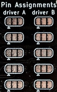
There are 5 sets of PCB jumpers for each motor driver IC, some or all of which can be used to reassign Arduino pins to the various logic functions. The table below lists them in order as they appear on the PCB:
| Function | Driver A Default | Driver A Alternate | Driver B Default | Driver B Alternate |
|---|---|---|---|---|
| PWM | D3 | D2 | D11 | D5 |
| Fault | A4 | D0 | A5 | D1 |
| Brake | D9 | D7 | D8 | D6 |
| Direction | D12 | D10 | D13 | D4 |
| Current sense | A0 | A2 | A1 | A3 |
There are 4 sets of PCB jumpers to change the way power is handled on the board. One on the top of the board, and 3 on the bottom, shown here:
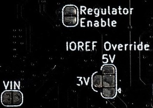
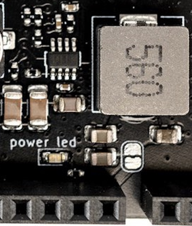
| Jumper | Function |
|---|---|
| Regulator Enable | Defaults to ENABLED, cut between pads to DISABLE onboard 7.2V regulator |
| IOREF Override | Defaults to IOREF used as power source, cut and then solder to either 5V or 3V3 to power logic and current sense |
| VIN | Defaults to NOT connected. CAUTION: soldering these pads CONNECTS motor power to VIN and should not be needed |
| Regulator to VIN (unlabelled) | Defaults to ON, cut to stop providing regulated 7.2V power to VIN to power the Arduino |
The bill of materials spreadsheet above is optimised for manufacture at JLCPCB (https://jlcpcb.com/) at present, and will allow assembly of all components except the DC barrel jack, motor output connectors and Arduino shield stackable headers.
For best performance, 1oz copper for both outer and inner layers of this 4-layer PCB are safest. Of course 2oz copper can be specified, but this is not deemed necessary from testing so far and cost may be prohibitive. Also, using FR-4 TG155 will give additional safety margin. The design can be made lead-free, provided all components are also lead-free types. JLCPCB currently does not have lead-free connectors for DCC track or DC input power, so those components are not in the default Bill of Materials (BOM).
It is possibile to stack two EX-MotorShield8874s, though for use in in DCC-EX EX-CommandStation this is not fully tested or yet supported by software configuration.

There are two different proposed operating modes possible:
This information is provided for reference. Documentation will be updated when both of these modes are fully tested and configured in DCC-EX EX-CommandStation.
CAUTIONARY NOTE: Only one EX-MotorShield8874 should provide power to the underlying motherboard from the DCC power feed! The jumper connecting the top VIN feed pin from the onboard 7.2V regulator to the Arduino sheild connectors must be cut on one of the stacked shields. It is also advisable to cut the ENABLE pin for the onboard regulator as that will turn it off completely as well. (See documentation of Power Configuration PCB Jumpers, above!)
| Qty | Value | Footprint | References |
|---|---|---|---|
| 15 | Jumper_3 | Jumper:SolderJumper-3_P1.3mm_Bridged12_RoundedPad1.0x1.5mm | JP101, JP102, JP103, JP105, JP106, JP108, JP109, JP110, JP111, JP112, JP113, JP114, JP115, JP116, JP117 |
| 11 | 100n | _my:C_1005_(0402) | C101, C104, C107, C108, C114, C115, C201, C207, C223, C224, C225 |
| 11 | 47k | _my:R_1005_(0402) | R101, R102, R105, R106, R107, R108, R113, R204, R205, R207, R208 |
| 8 | 22u | Capacitor_SMD:C_0805_2012Metric | C111, C204, C205, C206, C219, C220, C221, C222 |
| 6 | - | Capacitor_SMD:C_1210_3225Metric_Pad1.33x2.70mm_HandSolder | C213, C214, C215, C216, C217, C218 |
| 5 | 10u VM | Capacitor_SMD:C_1206_3216Metric | C102, C105, C210, C211, C212 |
| 4 | 0603_LED_Red | LED_SMD:LED_0603_1608Metric | D101, D102, D103, D104 |
| 3 | - | _my:PinHeader_01x03_P2.5mm_Vertical_min | J102, J104, J202 |
| 3 | 100n VM | _my:C_1005_(0402) | C103, C106, C203 |
| 3 | 470k | _my:R_1005_(0402) | R114, R201, R203 |
| 3 | Fiducial | Fiducial:Fiducial_1mm_Mask2mm | FID104, FID105, FID106 |
| 3 | Jumper_4 | _my:SolderJumper-4 | JP104, JP107, JP205 |
| 3 | Toolinghole_jlc | _my:toolinghole_jlc | FID101, FID102, FID103 |
| 2 | 100u VM | Capacitor_SMD:CP_Elec_6.3x7.7 | C208, C209 |
| 2 | 10k | Resistor_SMD:R_0805_2012Metric_Pad1.20x1.40mm_HandSolder | R103, R104 |
| 2 | 1k43 | _my:R_1005_(0402) | R109, R110 |
| 2 | 22n | _my:C_1005_(0402) | C112, C113 |
| 2 | 22n VM | _my:C_1005_(0402) | C109, C110 |
| 2 | 732R | _my:R_1005_(0402) | R111, R112 |
| 2 | AO3400A | Package_TO_SOT_SMD:SOT-23 | Q101, Q102 |
| 2 | DRV8874PWPR | _my:HTSSOP-16-1EP_4.4x5mm_P0.65mm_EP3.4x5mm_Mask2.46_HiAmp | U104, U105 |
| 2 | Jumper_2 | Jumper:SolderJumper-2_P1.3mm_Bridged2Bar_RoundedPad1.0x1.5mm | JP202, JP203 |
| 2 | Jumper_2_o | Jumper:SolderJumper-2_P1.3mm_Open_RoundedPad1.0x1.5mm | JP201, JP204 |
| 2 | MC 1,5/ 2-G-3,5 | _my:PhoenixContact_MC_1,5_2-G-3.5_1x02_P3.50mm_Horizontal_edited | J101, J103 |
| 1 | - | _my:PinHeader_1x02_P2.54mm_Vertical_min | J201 |
| 1 | 0603_LED_Green | LED_SMD:LED_0603_1608Metric | D202 |
| 1 | 10V | Diode_SMD:D_SOD-323 | D201 |
| 1 | 10u VM 0805 | Capacitor_SMD:C_0805_2012Metric | C202 |
| 1 | 20R | _my:R_1005_(0402) | R202 |
| 1 | 56uH | _my:L_PSPMAA0805 | L201 |
| 1 | 5k76 | _my:R_1005_(0402) | R206 |
| 1 | 74HC04 | Package_SO:SO-14_3.9x8.65mm_P1.27mm | U101 |
| 1 | 74HC08 | Package_SO:SO-14_3.9x8.65mm_P1.27mm | U102 |
| 1 | 74HC32 | Package_SO:SO-14_3.9x8.65mm_P1.27mm | U103 |
| 1 | AOD4185 | Package_TO_SOT_SMD:TO-252-2 | Q201 |
| 1 | Arduino_UNO_R3 | Module:Arduino_UNO_R3 | A101 |
| 1 | Barrel_Jack_MountingPin | _my:BarrelJack_2.1mm | J203 |
| 1 | Conn_01x04_f | Connector_PinSocket_2.54mm:PinSocket_1x04_P2.54mm_Vertical | J107 |
| 1 | Conn_02x04_smd | Connector_PinHeader_2.54mm:PinHeader_2x04_P2.54mm_Vertical_SMD | J106 |
| 1 | LMV321 | Package_TO_SOT_SMD:SOT-23-5 | U106 |
| 1 | LOGO | _my:DCC-EX-30mm | G*** |
| 1 | LOGO | _my:DCC-EX-15mm | G*** |
| 1 | LOGO | _my:semify_big | G*** |
| 1 | MP9942GJ | _my:TSOT23-8 | U201 |
| 1 | STEMMA QT | Connector_JST:JST_SH_SM04B-SRSS-TB_1x04-1MP_P1.00mm_Horizontal | J105 |
| 1 | Switch | _my:SW_SPST_TS-1088-AR02016 | SW101 |
The 122 most common of 123 parts.
It measures 65.9 × 52.7 mm and has 4 copper layers, 1.6 mm thick.
123 parts, built around the ARDUINO UNO R3, LMV321, MP9942GJ-Z and 74HC04D. The full list of its parts is on this page, with links to each part's symbol and footprint where PCBKit's library has them.
From the DCC-EX/EX-Hardware repository on GitHub, at the commit this page was made from: the board is EX-Motorshield8874/motor-shield.kicad_pcb and its schematic EX-Motorshield8874/motor-shield.kicad_sch. PCBKit opens the board in the browser, with nothing to install.
Its repository publishes it under the CERN-OHL-W-2.0 licence: you may reuse it on that licence's terms (keep the author's notice, and for a copyleft licence share your changes alike).

Filip-Kin/frc-radio-kiosk
Bench box that powers and configures FRC radios: dual-mode PoE (802.3at via LTC4279, passive 12 V via TPS26600), USB-C PD or DC in, 15.6 V out for the Toughbook, 4x CR123A backup, STM32F072 firmware.

slu4coder/Minimal-UART-Computer-1-2
Legacy: Version 1 and 2 of my TTL-only CPU featuring UART I/O, an expansion port, 512KB SSD at up to 10MHz clock speed

slu4coder/Minimal-64-Home-Computer
Legacy: Full TTL-only home computer with VGA and PS/2 and twice the processing power of a Commodore 64

artemisamsx/artemisa
Schematics, PCB designs and HDL simulations to build a 8-bits MSX computer


46nori/Z80Atmega128
Real Z80A system with I/O emulated by AVR(ATmega128)

EwoudVV/arpeggiator
12-note analog arpeggiator with a 1/2/3 octave range, custom pcb and printed case