4 layers17.8 × 43.2 mm
SimpleFOCNano
runger1101001/SimpleFOCNano
A small BLDC driver shield in Arduino Nano form-factor.
42 parts1

 runger1101001/SimpleFOCNano1
A small BLDC driver shield in Arduino Nano form-factor.
SimpleFOCNano Panel is an open-source printed circuit board by runger1101001, from the runger1101001/SimpleFOCNano repository on GitHub. It is a 4-layer board of 103.9 × 73.3 mm with 510 parts on 312 nets, routed with 2,454 tracks and 312 vias.
It is built around the TPSM33625RDNR, DRV8313RHH and PMEG40T30ERX. Its parts include 108 capacitors, 72 resistors, 24 connectors, 18 diodes and 12 ICs. It belongs with the AVR (ATmega, ATtiny) boards of this library.


A small BLDC driver shield in Arduino Nano form-factor.
Features:
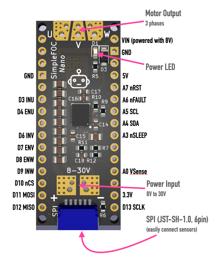
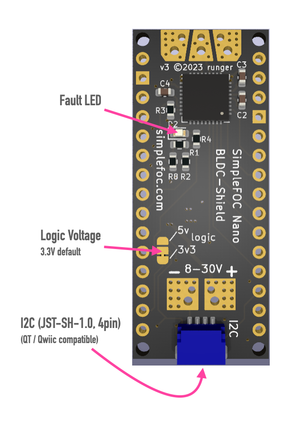
The board has the following connections.
Front:
Back:
The shield uses the following pinout on the nano:
| Pin | Purpose |
|---|---|
| D3 | PWM Input U |
| D6 | PWM Input V |
| D9 | PWM Input W |
| D4 | EN Input U |
| D7 | EN Input V |
| D8 | EN Input W |
| A0 | Bus Voltage Sense (analog) |
| A3 | Driver Sleep (active low, 10k pull-up) |
| A6 | Driver Fault (active low, open drain) |
| A7 | Driver Reset (active low, 10k pull-up) |
| VIN | Powered with 8V |
Note that the Nano's default lines for serial RX/TX are not used by the shield.
I2C and SPI are not used, but are routed to the shield's JST-SH-1.0 ports. They can also be used via the pin-headers. Pin D10 is used as the SPI nCS signal, and has a 10k pull-up resistor. Note that pins A4 and A5 (I2C lines SDA and SCL) have no additional pull-up resistors on the SimpleFOC Nano board.
The following are the routed pins:
| Pin | Purpose |
|---|---|
| D10 | SPI nCS |
| D11 | SPI MOSI |
| D12 | SPI MISO |
| D13 | SPI SCLK |
| A4 | I2C SDA |
| A5 | I2C SCL |
The board accepts power via its power input pads, you can solder cables, a 2.54mm spaced header, or 3mm spaced header to make the connection.
Power input is 8V - 30V, although in my tests the driver begins to operate at around 7V.
The on-board buck regulator produces 8V from the input voltage, which is provided to Arduino Nano on the VIN pin. The VIN pin is protected by a diode, so you can plug USB power into the Nano at the same time. If less than 8V is supplied to the SimpleFOCNano shield, the buck converter operates in full conduction, and the input voltage is provided on VIN. In my tests, 5V is enough to make any of the Ardunino Nano boards come to life.
When operating from battery power, this means you should really use a 3S-6S battery - 2S may be enough, but might be too little for the driver when partially discharged.
The solder jumper on the back of the board can be used to configure the logic voltage used by the shield to either 3.3V or 5V. The default setting is 3.3V and is correct for all the Nano boards except the original Nano and the Nano Every, for which the solder jumper should be changed to 5V.
When using the Nano shield with other MCU boards, select the voltage appropriate for the MCU board you are using. Make sure to connect either the 3.3V or the 5V header pin to the selected voltage.
To change the default configuration, use a sharp knife to carefully cut the existing solder pad connection at the point where it joins the pads, and lift the copper trace off the pcb.
Then use solder to create a new connection between the centre pad and the other solder pad.
After finishing, please check that the old pad is disconnected and the new pad is well connected using a multi-meter.
The SimpleFOC Nano is designed to connect directly underneath or on top of your Nano board using the standard Nano headers.
So if your Nano and/or SimpleFOC Nano shield came without headers soldered on, the first step is soldering headers. Of course, you can also connect it with jumper wires or by other means, in which case you can also connect any other type of MCU board supported by SimpleFOC. In this case check the connections carefully, and note which pins you use for what purpose on your MCU board. These instructions assume you're using some kind of Arduino Nano (all of them are supported) and connecting directly with headers.
It doesn't matter whether the SimpleFOC Nano shield is mounted above or below the Nano, you can solder the headers either way. If one of your boards already came with headers and the other did not, pay careful attention to solder the other board's headers (male/female, orientation) to match.
For the power input and motor output, you can solder either 2.54mm headers or 3.5mm terminal blocks to the shield, or you can solder wires directly to the solder pads.
Once the headers are soldered (and cooled) you can connect the boards.
At this point, if you apply 8V to 30V input power to the shield, the Arduino should be powered on also, and you should see green LEDs on both Arduino Nano and the shield. If so you are ready to try open-loop mode.
For closed loop mode, you must still connect a sensor. The Nano's I2C and SPI pins are free, and depending on the model of Nano these pins could also connect a ABZ type encoder.
A magnetic sensor like this AS5048A sensor connects directly to the SPI port on the SimpleFOC Nano shield.
TODO setup examples with pictures
The supply voltage is connected to pin A0 via 1/10 voltage divider. If you don't want this functionality, don't connect the A0 pin between the boards.
Simplest possible sketch for SimpleFOCNano:
#include <SimpleFOC.h>
#include <SimpleFOCDrivers.h>
#include <drivers/simplefocnano/SimpleFOCNanoDriver.h>

SimpleFOCNanoDriver driver = SimpleFOCNanoDriver();
BLDCMotor motor = BLDCMotor(7);

void setup() {
    driver.voltage_power_supply = driver.getBusVoltage(3.3f, 1024);
    driver.init();
    motor.linkDriver(driver);
    motor.voltage_limit = driver.voltage_limit / 2.0f;
    motor.controller = MotionControlMode::velocity_openloop;
    motor.init();
}

void loop(){
    motor.move(2.0f); // 2 rads per second, open-loop
}
The SimpleFOCNanoDriver is just a wrapper class around SimpleFOC's BLDCDriver3PWM that saves you having to configure the pins. You can also use the SimpleFOCNano shield using the standard BLDCDriver3PWM like in many of our examples. In this case, use the pin numbers as defined above.
Using SPI is easy, you can use the standard SPI object as the pins used by the SPI plug on the shield are the standard ones. Use pin 10 as the nCS signal.
Using I2C via the JST port on the shield is easy. Stemma/QT compatible I2C extension boards should plug directly to this port, the standard I2C pins for the Nano are used.
Further examples can be found in the SimpleFOCNanoDriver's code repository.
| Qty | Value | Footprint | References |
|---|---|---|---|
| 60 | 10uF 50V | Capacitor_SMD:C_0805_2012Metric | C1, C1, C1, C1, C1, C1, C10, C10, C10, C10, C10, C10, C11, C11, C11, C11 +44 |
| 36 | 10k | Resistor_SMD:R_0603_1608Metric | R1, R1, R1, R1, R1, R1, R2, R2, R2, R2, R2, R2, R3, R3, R3, R3 +20 |
| 24 | 2k2 | Resistor_SMD:R_0603_1608Metric | R4, R4, R4, R4, R11, R11, R11, R11, R11, R11, R12, R12, R12, R12, R12, R12 +8 |
| 18 | 100nF 50V | Capacitor_SMD:C_0603_1608Metric | C2, C2, C2, C2, C2, C2, C3, C3, C3, C3, C14, C14, C14, C14, C14, C14 +2 |
| 12 | 1uF 16V | Capacitor_SMD:C_0603_1608Metric | C15, C15, C15, C15, C15, C15, C18, C18, C18, C18, C18, C18 |
| 12 | 22uF 16V | Capacitor_SMD:C_0603_1608Metric | C16, C16, C16, C16, C16, C16, C17, C17, C17, C17, C17, C17 |
| 6 | 19k8 | Resistor_SMD:R_0603_1608Metric | R7, R7, R7, R7, R7, R7 |
| 6 | 470nF 16V | Capacitor_SMD:C_0603_1608Metric | C4, C4, C4, C4, C4, C4 |
| 6 | 70k | Resistor_SMD:R_0603_1608Metric | R10, R10, R10, R10, R10, R10 |
| 6 | Arduino_Nano_Socket | PCM_arduino-library:Arduino_Nano_Socket | XA1, XA1, XA1, XA1, XA1, XA1 |
| 6 | Conn_01x02 | runger:Power_Combo_Squarish | J1, J1, J1, J1, J1, J1 |
| 6 | Conn_01x04 | Connector_JST:JST_SH_SM04B-SRSS-TB_1x04-1MP_P1.00mm_Horizontal | J4, J4, J4, J4, J4, J4 |
| 6 | DRV8313RHH | Package_DFN_QFN:Texas_S-PVQFN-N36_EP4.4x4.4mm | U1, U1, U1, U1, U1, U1 |
| 6 | Green | LED_SMD:LED_0603_1608Metric | D1, D1, D1, D1, D1, D1 |
| 6 | PMEG40T30ER | Diode_SMD:Nexperia_CFP3_SOD-123W | D3, D3, D3, D3, D3, D3 |
| 6 | Phase_Pads | runger:Edge_Solderpads_3x_2.54and3.5_Squarish | J2, J2, J2, J2, J2, J2 |
| 6 | Red | LED_SMD:LED_0603_1608Metric | D2, D2, D2, D2, D2, D2 |
| 6 | Robo_Logo | runger:Robo_logo2 | L1, L1, L1, L1, L1, L1 |
| 6 | SPI | Connector_JST:JST_SH_SM06B-SRSS-TB_1x06-1MP_P1.00mm_Horizontal | J3, J3, J3, J3, J3, J3 |
| 6 | SW_SPDT | Jumper:SolderJumper-3_P1.3mm_Bridged12_RoundedPad1.0x1.5mm | SW1, SW1, SW1, SW1, SW1, SW1 |
| 6 | TPSM33625RDNR | runger:QFN-FCMOD11_RDN_TEX | U3, U3, U3, U3, U3, U3 |
The 252 most common of 510 parts.
runger1101001/SimpleFOCNano
A small BLDC driver shield in Arduino Nano form-factor.


stefanskotte/webadf
Web-based Amiga ADF library that mounts disks to a Gotek over WiFi


elrir01/AudioPico
This board receive audio from a BT source like a phone and outputs via a DAC the audio. It's an old project of mine but I've decided to publish it just now, so the full description is not ready and will be updated in…

JitterCompany/debug-tools
Collection of useful utility PCBs for development purposes


koson/3D-Printer-Board
A custom, high powered 3d printer controller board designed to run up to 9 stepper drivers, with various peripherals and controls.

FirstTestStation/Selftest_Board
KiCad PCB design utilized in the creation of the Selftest Board.
It measures 103.9 × 73.3 mm and has 4 copper layers, 1.6 mm thick.
510 parts, built around the TPSM33625RDNR, DRV8313RHH and PMEG40T30ERX. The full list of its parts is on this page, with links to each part's symbol and footprint where PCBKit's library has them.
From the runger1101001/SimpleFOCNano repository on GitHub, at the commit this page was made from: the board is SimpleFOCNano_Panel.kicad_pcb and its schematic SimpleFOCNano.kicad_sch. PCBKit opens the board in the browser, with nothing to install.
Its repository states no licence, so its author keeps all rights: ask runger1101001 before reusing the design.