2 layers31.6 × 96.7 mm
Thermometer esp8266-01s
Mael-Le-Garrec/ESP-01S_thermometer
This is a KiCad project to create a PCB with an ESP-01S and a DS18B20 thermometer
12 parts

 rmingon/PickOMatic-V21
One board to drive your entire pick-and-place machine: RISC-V CH32V317, 7 stepper channels, Ethernet, USB-C, vacuum and lighting control. Open hardware.
PickOMatic V2 is an open-source printed circuit board by rmingon, from the rmingon/PickOMatic-V2 repository on GitHub, published under the CERN-OHL-S-2.0 licence. It is a 4-layer board of 100 × 100 mm with 172 parts on 243 nets, routed with 1,687 tracks and 290 vias.
It is built around the SSP1117-3.3V, TPS562200DDC and AO3400A. Its parts include 54 capacitors, 41 resistors, 20 connectors, 11 ICs and 5 diodes. It belongs with the lEDs and displays and interfaces and adapters boards and the RISC-V boards of this library.


Place faster. Place smarter. The open-source motion controller that turns your pick-and-place ambitions into production reality.
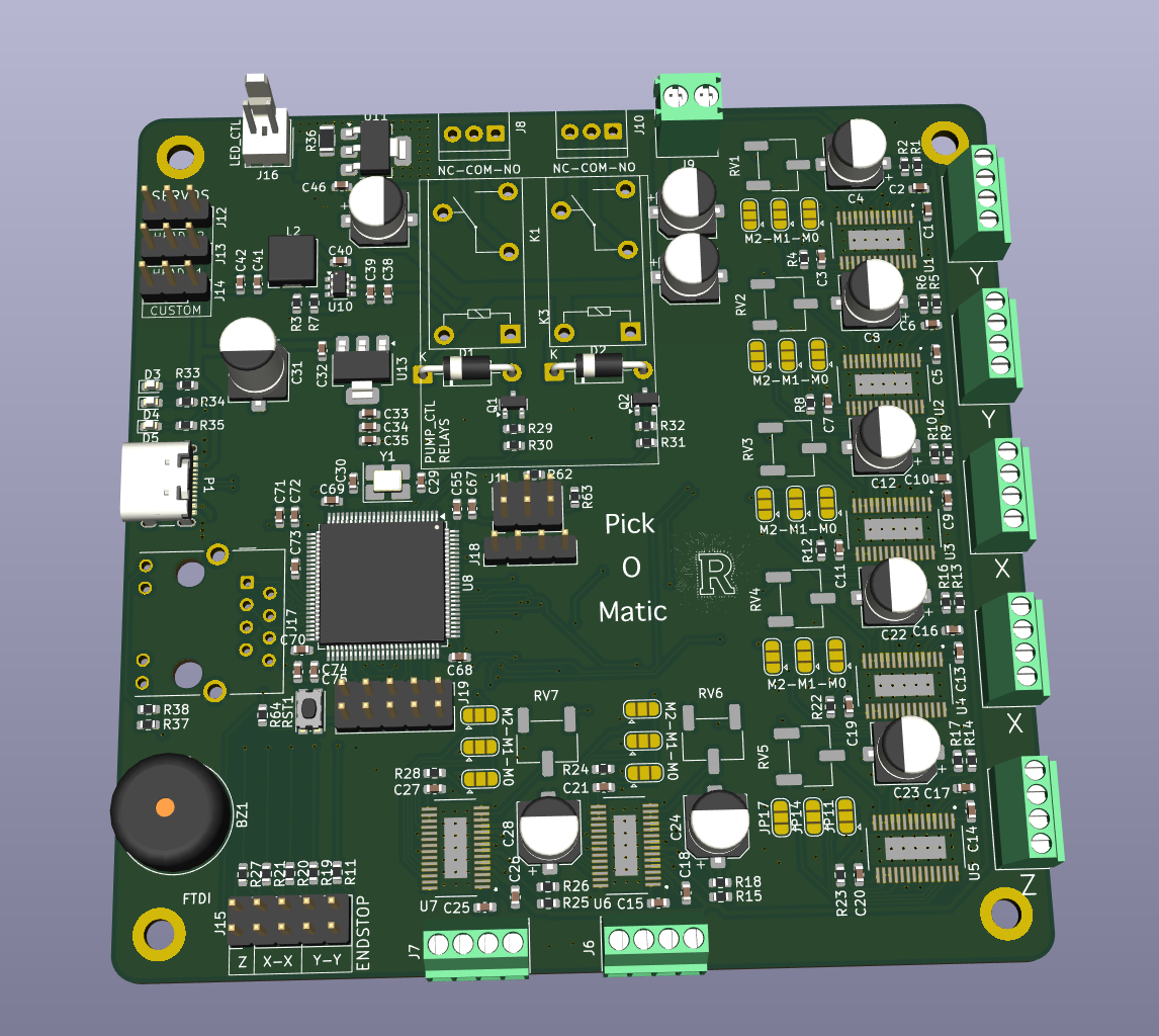




PickOMatic V2 is a professional-grade, all-in-one motion control board designed from the ground up for desktop pick-and-place machines. It is the second generation of the PickOMatic motion controller, rebuilt around a modern 32-bit RISC-V microcontroller with native Ethernet and USB-C connectivity.
One board drives the entire machine: gantry, picker heads, nozzles, vacuum, lighting and feedback, with no shields, no breakout spaghetti and no compromises.
| PickOMatic V1 | PickOMatic V2 | |
|---|---|---|
| Microcontroller | ATmega2560 @ 16 MHz (8-bit AVR) | CH32V317VCT6 (32-bit RISC-V) |
| Host link | USB-UART (CH340C) | Native USB-C + Ethernet (RJ45) |
| Stepper channels | 8 | 7 x DRV8825 with per-axis microstep jumpers |
| Debug / programming | AVR-ISP | SWD + FTDI UART + BOOT jumpers |
| Networking | None | On-board Ethernet PHY + magjack |
| PCB layout | Schematic |
|---|---|
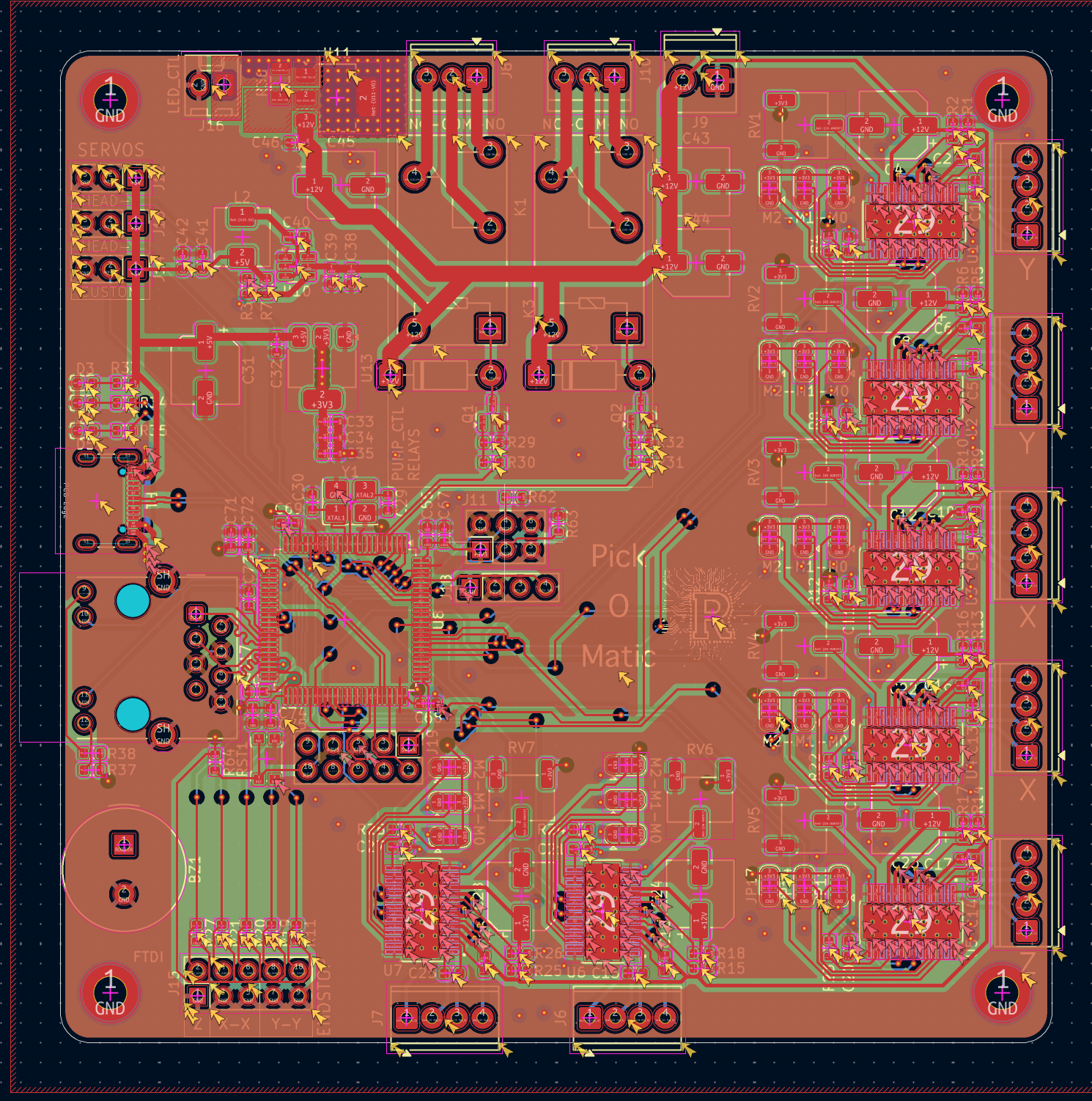 | 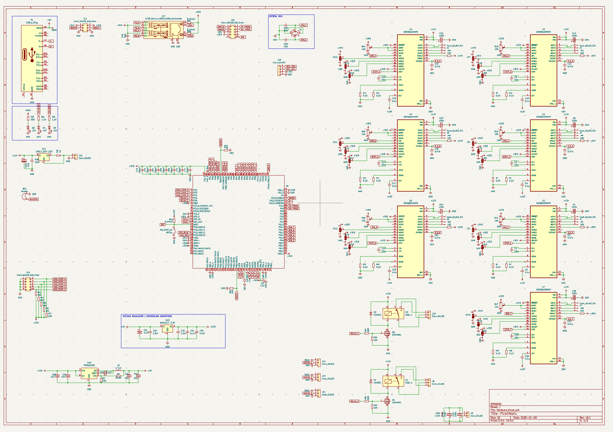 |
| Subsystem | Detail |
|---|---|
| MCU | WCH CH32V317VCT6, 32-bit RISC-V, LQFP-100, external crystal |
| Motion | 7 x DRV8825 stepper drivers (STEP/DIR), microstepping via M0/M1/M2 solder jumpers, current trim potentiometers |
| Axes | Dual-Y and dual-X gantry support, Z axis, auxiliary picker-head channels |
| Endstops | 5 inputs (Z, X-X, Y-Y) on a dedicated header |
| Servos | 3 PWM outputs for nozzle actuation |
| Pneumatics | Relay outputs with NC-COM-NO terminals for vacuum pump control |
| Lighting | Dedicated LED_CTL output for inspection lighting |
| Connectivity | USB-C, 10M Ethernet (RJ45 HR911105A), I²C expansion, FTDI UART |
| Debug | SWD (SWCLK/SWDIO), BOOT0/BOOT1 jumpers, reset button |
| Feedback | Buzzer, status LEDs |
| Power input | 12 V DC via screw terminal |
| Power rails | 12 V motor rail, 5 V and 3.3 V logic rails (TPS562200 buck converters + LDOs) |
| Form factor | 4-corner mounting holes, screw-terminal I/O on board edges |
PickOMatic-V2/
├── hardware/               # KiCad project (schematic + PCB)
│   ├── hardware.kicad_pro
│   ├── hardware.kicad_sch
│   └── hardware.kicad_pcb
├── 3d.png                  # 3D render of the assembled board
├── pcb.png                 # PCB layout view
├── schematic.png           # Full schematic
├── LICENSE                 # CERN-OHL-S v2
└── README.mdgit clone https://github.com/rmingon/PickOMatic-V2.githardware/hardware.kicad_pro in KiCad (version 8 or later recommended)Issues and pull requests are welcome. If you build a machine around PickOMatic V2, share it: photos, firmware ports and feeder designs all help the project grow.
This project is open-source hardware, released under the CERN Open Hardware Licence Version 2, Strongly Reciprocal (CERN-OHL-S-2.0).
You may use, study, modify, manufacture and distribute this design, provided that any modified versions are released under the same licence and that source is made available. See LICENSE for the full text.
Copyright © 2026 rmingon
PickOMatic V2, because your components deserve to be placed with confidence.
| Qty | Value | Footprint | References |
|---|---|---|---|
| 21 | SolderJumper_3_Open | Jumper:SolderJumper-3_P1.3mm_Open_RoundedPad1.0x1.5mm | JP1, JP2, JP3, JP4, JP10, JP11, JP12, JP13, JP14, JP15, JP16, JP17, JP18, JP19, JP20, JP21 +5 |
| 15 | 10K | Resistor_SMD:R_0603_1608Metric | R3, R4, R8, R11, R12, R19, R20, R21, R22, R23, R24, R27, R28, R29, R32 |
| 14 | 0.10 | Resistor_SMD:R_0603_1608Metric | R1, R2, R5, R6, R9, R10, R13, R14, R15, R16, R17, R18, R25, R26 |
| 10 | 100n | Capacitor_SMD:CP_Elec_6.3x5.7 | C4, C8, C12, C22, C23, C24, C28, C43, C44, C45 |
| 7 | 0.1u | Capacitor_SMD:C_0603_1608Metric | C2, C6, C10, C16, C17, C18, C26 |
| 7 | 0.47u | Capacitor_SMD:C_0603_1608Metric | C3, C7, C11, C19, C20, C21, C27 |
| 7 | 100nF | Capacitor_SMD:C_0603_1608Metric | C67, C68, C69, C70, C71, C74, C75 |
| 7 | 10k | Potentiometer_SMD:Potentiometer_Bourns_3269W_Vertical | RV1, RV2, RV3, RV4, RV5, RV6, RV7 |
| 7 | 10n | Capacitor_SMD:C_0603_1608Metric | C1, C5, C9, C13, C14, C15, C25 |
| 7 | Conn_01x04_Pin | TerminalBlock_Phoenix:TerminalBlock_Phoenix_MPT-0,5-4-2.54_1x04_P2.54mm_Horizontal | J1, J2, J3, J4, J5, J6, J7 |
| 7 | DRV8825PWPR | DRV8825PWPR:IC_TPS61196PWPRQ1 | U1, U2, U3, U4, U5, U6, U7 |
| 4 | 10pf | Capacitor_SMD:C_0603_1608Metric | C29, C30, C46, C55 |
| 3 | 3.3uf | Capacitor_SMD:C_0603_1608Metric | C32, C33, C35 |
| 3 | Conn_01x03 | Connector_PinHeader_2.54mm:PinHeader_1x03_P2.54mm_Vertical | J12, J13, J14 |
| 3 | LED | LED_SMD:LED_0603_1608Metric | D3, D4, D5 |
| 3 | R_Small | Resistor_SMD:R_0603_1608Metric | R37, R38, R64 |
| 2 | 1.1K | Resistor_SMD:R_0603_1608Metric | R34, R35 |
| 2 | 10k | Resistor_SMD:R_0603_1608Metric | R62, R63 |
| 2 | 10u | Capacitor_SMD:C_0603_1608Metric | C38, C39 |
| 2 | 1N4001 | Diode_THT:D_DO-41_SOD81_P10.16mm_Horizontal | D1, D2 |
| 2 | 1µf | Capacitor_SMD:C_0603_1608Metric | C72, C73 |
| 2 | 22u | Capacitor_SMD:C_0603_1608Metric | C41, C42 |
| 2 | 680 | Resistor_SMD:R_0603_1608Metric | R30, R31 |
| 2 | AO3400A | Package_TO_SOT_SMD:SOT-23 | Q1, Q2 |
| 2 | Conn_01x03 | TerminalBlock_TE-Connectivity:TerminalBlock_TE_282834-3_1x03_P2.54mm_Horizontal | J8, J10 |
| 2 | Conn_02x05_Odd_Even | Connector_PinHeader_2.54mm:PinHeader_2x05_P2.54mm_Vertical | J15, J19 |
| 2 | G5Q-1 | Relay_THT:Relay_SPDT_Omron-G5Q-1 | K1, K3 |
| 1 | 0.1uF | Capacitor_SMD:C_0603_1608Metric | C34 |
| 1 | 0.1µF | Capacitor_SMD:C_0603_1608Metric | C40 |
| 1 | 12 | Resistor_SMD:R_1206_3216Metric | R36 |
| 1 | 33.0K | Resistor_SMD:R_0603_1608Metric | R7 |
| 1 | 4.7uH | Inductor_SMD:L_Chilisin_BMRA00050520 | L2 |
| 1 | 47uF | Capacitor_SMD:CP_Elec_6.3x9.9 | C31 |
| 1 | 500 | Resistor_SMD:R_0603_1608Metric | R33 |
| 1 | Buzzer | Buzzer_Beeper:Buzzer_TDK_PS1240P02BT_D12.2mm_H6.5mm | BZ1 |
| 1 | Conn_01x02 | Connector_Molex:Molex_KK-254_AE-6410-02A_1x02_P2.54mm_Vertical | J16 |
| 1 | Conn_01x02 | TerminalBlock_Phoenix:TerminalBlock_Phoenix_PT-1,5-2-3.5-H_1x02_P3.50mm_Horizontal | J9 |
| 1 | Conn_01x04 | Connector_PinHeader_2.54mm:PinHeader_1x04_P2.54mm_Vertical | J18 |
| 1 | Conn_02x03_Odd_Even | Connector_PinHeader_2.54mm:PinHeader_2x03_P2.54mm_Vertical | J11 |
| 1 | Crystal_GND24 | Crystal:Crystal_SMD_3225-4Pin_3.2x2.5mm_HandSoldering | Y1 |
| 1 | LM317_SOT-223 | Package_TO_SOT_SMD:SOT-223-3_TabPin2 | U11 |
| 1 | LOGO | R-logo:R-logo | G*** |
| 1 | RJ45_Hanrun_HR911105A_Horizontal | Connector_RJ:RJ45_Hanrun_HR911105A_Horizontal | J17 |
| 1 | SSP1117-3.3V | Package_TO_SOT_SMD:SOT-223-3_TabPin2 | U13 |
| 1 | SW_DPST_x2 | Button_Switch_SMD:SW_Push_1P1T_NO_CK_KMR2 | RST1 |
| 1 | TPS562200 | Package_TO_SOT_SMD:SOT-23-6 | U10 |
| 1 | USB_C_Plug | Connector_USB:USB_C_Receptacle_GCT_USB4105-xx-A_16P_TopMnt_Horizontal | P1 |
| 1 | ~ | Package_QFP:LQFP-100_14x14mm_P0.5mm | U8 |
The 168 most common of 172 parts.
Mael-Le-Garrec/ESP-01S_thermometer
This is a KiCad project to create a PCB with an ESP-01S and a DS18B20 thermometer

kabidey/someda-claude-plugin
This plugin puts the someda engine behind three slash commands. In a conversation, Claude writes the circuit as a small JSON plan: real parts with datasheet pinouts, nets, and intent such as "USB-C on the top edge".


rmingon/Falcon-Edge
A 3D-printable flying-wing airframe with a custom ESP32 flight computer—open hardware you can solder, screw together, and fly.

bastian-bou/NixieNTPClock
Nixie clock around ESP32 connected to a NTP server

vatsalbansal123/reaction-wheel-controller-pcb
Open-source FOC motor controller PCB for a reaction wheel — STM32G431 + DRV8311H driving a BLDC motor, with CAN bus interface. Designed in KiCad.

nyuad-space/dumpling
Modular payload for high-speed logging and benchmarking of COTS sensors, enabling real-world performance data and open sharing.

It measures 100 × 100 mm and has 4 copper layers, 1.6 mm thick.
172 parts, built around the SSP1117-3.3V, TPS562200DDC and AO3400A. The full list of its parts is on this page, with links to each part's symbol and footprint where PCBKit's library has them.
From the rmingon/PickOMatic-V2 repository on GitHub, at the commit this page was made from: the board is hardware/hardware.kicad_pcb and its schematic hardware/hardware.kicad_sch. PCBKit opens the board in the browser, with nothing to install.
Its repository publishes it under the CERN-OHL-S-2.0 licence: you may reuse it on that licence's terms (keep the author's notice, and for a copyleft licence share your changes alike).