2 layers22 × 22 mm
02 03 IMU BMI088 SPI
nyuad-space/dumpling
Modular payload for high-speed logging and benchmarking of COTS sensors, enabling real-world performance data and open sharing.
17 parts1

 nyuad-space/dumpling1
Modular payload for high-speed logging and benchmarking of COTS sensors, enabling real-world performance data and open sharing.
Dumpling Main is an open-source printed circuit board by nyuad-space, from the nyuad-space/dumpling repository on GitHub. It is a 6-layer board of 75 × 135.2 mm with 370 parts on 622 nets, routed with 4,807 tracks and 732 vias.
It is built around the W25Q128JVSIQ, USBLC6-2SC6 and TPS562200DDC, with the MPU-6050, WS2812B-2020 and AO3401A among its other parts. Its parts include 107 capacitors, 84 resistors, 31 ICs, 23 connectors and 18 diodes. It belongs with the sensors and measurement boards and the STM32 boards of this library.


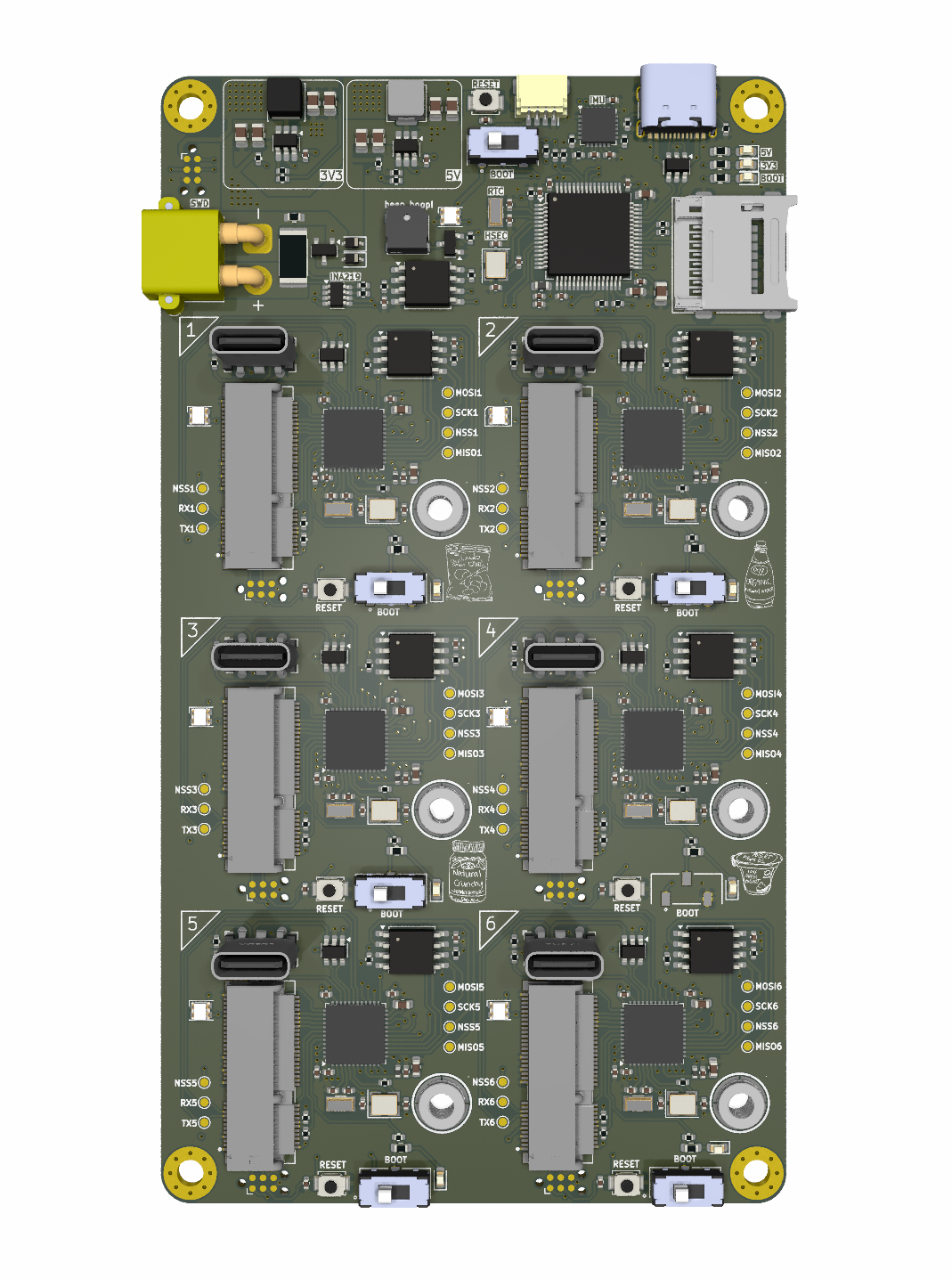
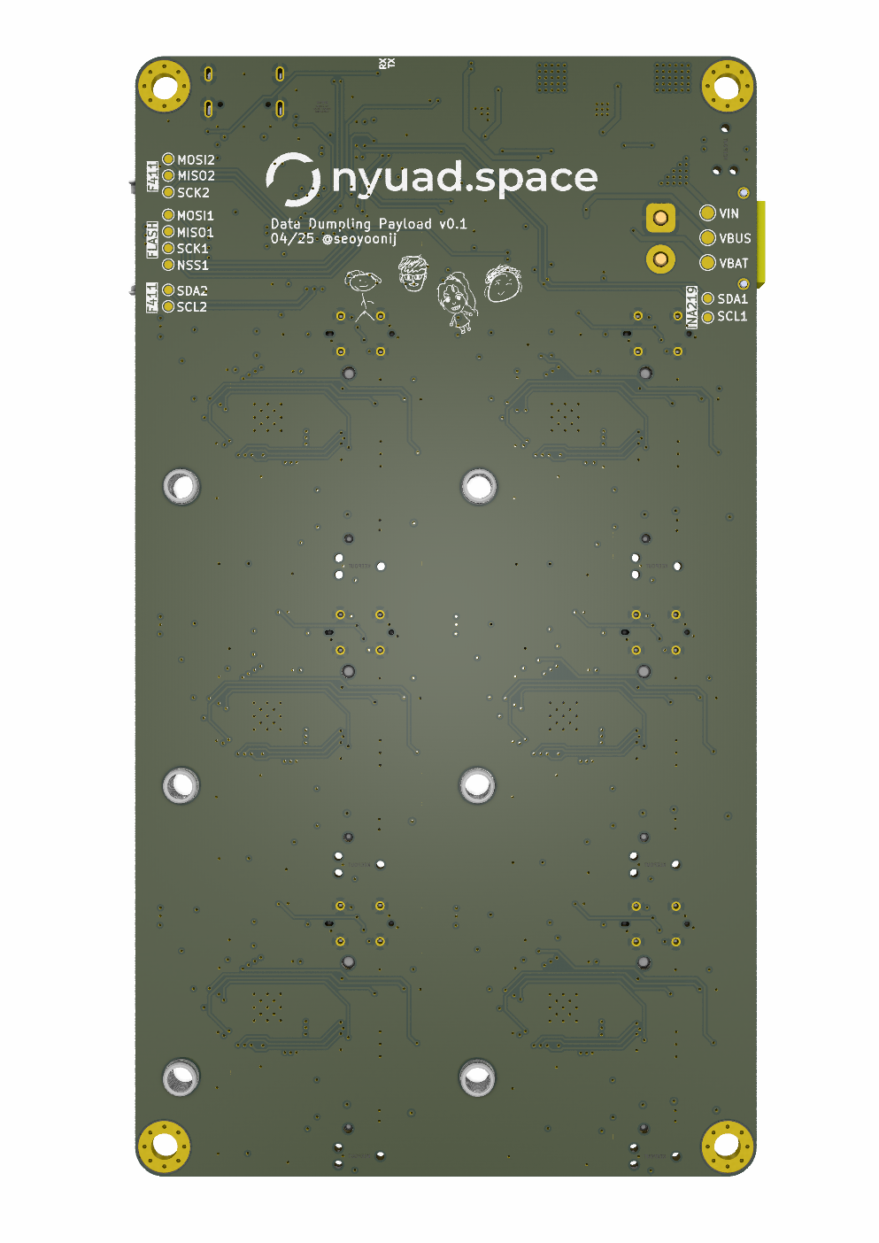
Data Dumpling is a modular, high-speed data logger for MEMS sensors, designed as a payload for our experimental sounding rocket Stage Fright (2025). It enables real-time characterization and benchmarking of commercial sensors in demanding flight environments. The project aims to support sensor research and promote scalable, plug-and-play architectures for future space missions.
| Type | Components |
|---|---|
| Main MCU | STM32F405RGT |
| Coprocessor | STM32F411CEU6 |
| IMUs | LSM6DSO32, BMI088 |
| Barometers | DPS310XTSA1, BMP390L |
| Magnetometer | LIS2MDLTR |
| Temperature | HDC3022DEJR |
| Flash | 16MB SPI NOR Flash per sensor board |
| Recovery | SD card slot for post-flight data offload |
Each STM32 microcontroller is programmed via built-in USB DFU bootloader.
Each sensor board follows this universal sequence:
Use the files, hardware, and software in this repository at your own risk.
We assume no liability for hardware damage, software malfunction, or unexpected behavior, particularly during live flight testing.
Always validate your configuration through extensive ground testing.
| Qty | Value | Footprint | References |
|---|---|---|---|
| 52 | 100n | Capacitor_SMD:C_0402_1005Metric | C1, C10, C13, C14, C19, C20, C22, C24, C28, C29, C33, C37, C100, C101, C103, C104 +36 |
| 29 | 10k | Resistor_SMD:R_0402_1005Metric | R2, R4, R10, R12, R14, R15, R17, R21, R31, R32, R33, R34, R35, R40, R41, R45 +13 |
| 18 | 4.7k | Resistor_SMD:R_0402_1005Metric | R22, R23, R24, R25, R29, R30, R42, R43, R51, R52, R60, R61, R69, R70, R78, R79 +2 |
| 16 | 5.1k | Resistor_SMD:R_0402_1005Metric | R6, R7, R18, R19, R38, R39, R47, R48, R56, R57, R65, R66, R74, R75, R82, R83 |
| 14 | 10p | Capacitor_SMD:C_0402_1005Metric | C11, C12, C16, C27, C30, C44, C54, C57, C67, C70, C80, C83, C93, C96 |
| 14 | 15p | Capacitor_SMD:C_0402_1005Metric | C3, C4, C17, C18, C23, C25, C55, C56, C68, C69, C81, C82, C94, C95 |
| 9 | 2.2k | Resistor_SMD:R_0603_1608Metric | R3, R11, R20, R36, R37, R46, R55, R64, R73 |
| 9 | LED | LED_SMD:LED_0603_1608Metric | D1, D2, D4, D6, D9, D11, D13, D15, D17 |
| 8 | 2.2u | Capacitor_SMD:C_0603_1608Metric | C15, C26, C35, C36, C53, C66, C79, C92 |
| 7 | 25MHz | Crystal:Crystal_SMD_Abracon_ABM8G-4Pin_3.2x2.5mm | HSE1, HSE2, HSE3, HSE4, HSE5, HSE6, HSE7 |
| 7 | 32.768kHz | Crystal:Crystal_SMD_3215-2Pin_3.2x1.5mm | Y1, Y2, Y3, Y4, Y5, Y6, Y7 |
| 7 | Conn_ARM_SWD_TagConnect_TC2030-NL | Connector:Tag-Connect_TC2030-IDC-NL_2x03_P1.27mm_Vertical | J1, J6, J9, J12, J15, J18, J21 |
| 7 | LOGO | LOGO | G***, G***, G***, G***, G***, G***, G*** |
| 7 | SW_SPDT | JS102011JCQN:SW_JS102011JCQN | SW1, SW4, SW6, SW8, SW10, SW12, SW14 |
| 7 | SW_SPST | Button_Switch_SMD:SW_SPST_B3U-1000P | SW2, SW3, SW5, SW7, SW9, SW11, SW13 |
| 7 | USBLC6-2SC6 | Package_TO_SOT_SMD:SOT-23-6 | U2, U6, U11, U14, U17, U20, U23 |
| 7 | W25Q128JVS | Package_SO:SOIC-8_5.3x5.3mm_P1.27mm | U3, U8, U10, U12, U15, U18, U24 |
| 7 | WS2812B-2020 | LED_SMD:LED_WS2812B-2020_PLCC4_2.0x2.0mm | D7, D8, D10, D12, D14, D16, D18 |
| 6 | 1u | Capacitor_SMD:C_0603_1608Metric | C21, C50, C63, C76, C89, C102 |
| 6 | 600 | Inductor_SMD:L_0402_1005Metric | FB2, FB3, FB4, FB5, FB6, FB7 |
| 6 | 620 | Resistor_SMD:R_0402_1005Metric | R13, R26, R44, R53, R62, R71 |
| 6 | MICROMOD-2222-C | mdot2:TE_2199119-4 | J7, J10, J13, J16, J19, J22 |
| 6 | SMTSOM2_525STR | SMTSOM2.525STR:SMD_BD5.6-D4.1 | U21, U27, U28, U29, U30, U31 |
| 6 | STM32F411CEUx | Package_DFN_QFN:QFN-48-1EP_7x7mm_P0.5mm_EP5.6x5.6mm | U4, U5, U13, U16, U19, U22 |
| 6 | USB_C_Receptacle_USB2.0_16P | Connector_USB:USB_C_Receptacle_G-Switch_GT-USB-7051x | J8, J11, J14, J17, J20, J23 |
| 5 | 10u | Capacitor_SMD:C_0805_2012Metric | C2, C31, C32, C39, C40 |
| 4 | 22u | Capacitor_SMD:C_0805_2012Metric | C34, C38, C42, C43 |
| 4 | MountingHole | MountingHole:MountingHole_3.2mm_M3_Pad_Via | H1, H2, H3, H4 |
| 4 | SPI1 | TestPoint:TestPoint_Pad_D1.0mm | TP5, TP6, TP7, TP8 |
| 4 | flsh1 | TestPoint:TestPoint_Pad_D1.0mm | TP19, TP24, TP28, TP32 |
| 4 | flsh2 | TestPoint:TestPoint_Pad_D1.0mm | TP25, TP29, TP33, TP35 |
| 4 | flsh3 | TestPoint:TestPoint_Pad_D1.0mm | TP14, TP15, TP16, TP17 |
| 4 | flsh4 | TestPoint:TestPoint_Pad_D1.0mm | TP23, TP26, TP27, TP34 |
| 4 | flsh5 | TestPoint:TestPoint_Pad_D1.0mm | TP40, TP41, TP42, TP43 |
| 4 | flsh6 | TestPoint:TestPoint_Pad_D1.0mm | TP47, TP48, TP49, TP50 |
| 3 | SPI2 | TestPoint:TestPoint_Pad_D1.0mm | TP9, TP10, TP11 |
| 3 | TestPoint | TestPoint:TestPoint_Pad_D1.5mm | VBAT1, VBUS1, VIN1 |
| 2 | 0.22u | Capacitor_SMD:C_0402_1005Metric | C106, C107 |
| 2 | D_Schottky | Diode_SMD:D_SOD-323 | D3, D5 |
| 2 | I2C1 | TestPoint:TestPoint_Pad_D1.0mm | TP1, TP2 |
| 2 | I2C2 | TestPoint:TestPoint_Pad_D1.0mm | TP3, TP4 |
| 2 | RF1 | TestPoint:TestPoint_Pad_D1.0mm | TP30, TP31 |
| 2 | RF2 | TestPoint:TestPoint_Pad_D1.0mm | TP36, TP90 |
| 2 | RF3 | TestPoint:TestPoint_Pad_D1.0mm | TP18, TP21 |
| 2 | RF4 | TestPoint:TestPoint_Pad_D1.0mm | TP37, TP38 |
| 2 | RF5 | TestPoint:TestPoint_Pad_D1.0mm | TP44, TP45 |
| 2 | RF6 | TestPoint:TestPoint_Pad_D1.0mm | TP51, TP52 |
| 2 | TPS562200 | Package_TO_SOT_SMD:SOT-23-6_Handsoldering | U25, U26 |
| 1 | 0.01 | Resistor_SMD:R_2512_6332Metric | R28 |
| 1 | 100k | Resistor_SMD:R_0603_1608Metric | R8 |
| 1 | 10n | Capacitor_SMD:C_0402_1005Metric | C105 |
| 1 | 1k | Resistor_SMD:R_0402_1005Metric | R9 |
| 1 | 1u | Capacitor_SMD:C_0402_1005Metric | C6 |
| 1 | 3.3u | Inductor_SMD:L_Changjiang_FNR4030S | L2 |
| 1 | 33.2k | Resistor_SMD:R_0402_1005Metric | R16 |
| 1 | 4.7u | Inductor_SMD:L_Changjiang_FXL0420 | L3 |
| 1 | 54.9k | Resistor_SMD:R_0402_1005Metric | R27 |
| 1 | 600 | Inductor_SMD:L_0603_1608Metric | FB1 |
| 1 | 620 | Capacitor_SMD:C_0402_1005Metric | R1 |
| 1 | AO3401A | Package_TO_SOT_SMD:SOT-23 | Q1 |
| 1 | Buzzer | FST-5030:BUZ-SMD_FST-5030 | BZ1 |
| 1 | CS1 | TestPoint:TestPoint_Pad_D1.0mm | TP12 |
| 1 | CS2 | TestPoint:TestPoint_Pad_D1.0mm | TP20 |
| 1 | CS3 | TestPoint:TestPoint_Pad_D1.0mm | TP13 |
| 1 | CS4 | TestPoint:TestPoint_Pad_D1.0mm | TP22 |
| 1 | CS5 | TestPoint:TestPoint_Pad_D1.0mm | TP39 |
| 1 | CS6 | TestPoint:TestPoint_Pad_D1.0mm | TP46 |
| 1 | INA219AxDCN | Package_TO_SOT_SMD:SOT-23-8 | U9 |
| 1 | MPU-6050 | Sensor_Motion:InvenSense_QFN-24_4x4mm_P0.5mm | U7 |
| 1 | Micro_SD_Card | Connector_Card:microSD_HC_Molex_47219-2001 | J2 |
| 1 | S8050 | Package_TO_SOT_SMD:SOT-23 | Q2 |
| 1 | SM04B-SRSS-TB | Connector_JST:JST_SH_SM04B-SRSS-TB_1x04-1MP_P1.00mm_Horizontal | J5 |
| 1 | STM32F405RGTx | Package_QFP:LQFP-64_10x10mm_P0.5mm | U1 |
| 1 | USB_C_Receptacle_USB2.0_16P | Connector_USB:USB_C_Receptacle_G-Switch_GT-USB-7010ASV | J3 |
| 1 | XT30PW-M | Connector_AMASS:AMASS_XT30PW-M_1x02_P2.50mm_Horizontal | J4 |
nyuad-space/dumpling
Modular payload for high-speed logging and benchmarking of COTS sensors, enabling real-world performance data and open sharing.

nyuad-space/dumpling
Modular payload for high-speed logging and benchmarking of COTS sensors, enabling real-world performance data and open sharing.

nyuad-space/dumpling
Modular payload for high-speed logging and benchmarking of COTS sensors, enabling real-world performance data and open sharing.

nyuad-space/dumpling
Modular payload for high-speed logging and benchmarking of COTS sensors, enabling real-world performance data and open sharing.

nasheed-x/aether
Aether is a versatile flight computer for testing flight hardware and software, focusing on sensor fusion to monitor rocket states and interface with on-board systems.

copperheadhq/copperhead-stm32-data-logger
Portable STM32L433 data logger, 50 × 70 mm, four layers, microSD, USB-C LiPo charging. Designed with copperhead. Never built: do not order expecting it to work.


kabidey/someda-claude-plugin
This plugin puts the someda engine behind three slash commands. In a conversation, Claude writes the circuit as a small JSON plan: real parts with datasheet pinouts, nets, and intent such as "USB-C on the top edge".

Lukikato101/AMR_Robot-Trash-Collector-Simple-PCB
Autonomous trash collector robot simulation with AI object detection and monitoring dashboard.


It measures 75 × 135.2 mm and has 6 copper layers, 1.6 mm thick.
370 parts, built around the W25Q128JVSIQ, USBLC6-2SC6, TPS562200DDC and MPU-6050. The full list of its parts is on this page, with links to each part's symbol and footprint where PCBKit's library has them.
From the nyuad-space/dumpling repository on GitHub, at the commit this page was made from: the board is 01_main-board/Dumpling_Main.kicad_pcb and its schematic 01_main-board/Dumpling_Main.kicad_sch. PCBKit opens the board in the browser, with nothing to install.
Its repository states no licence, so its author keeps all rights: ask nyuad-space before reusing the design.