4 layers30 × 30 mm
Controller
andrewsharmon/rp2350-stepper-controller
Low-cost 10-axis sine-microstepping controller for small steppers on the RP2350 (PIO + DMA). WIP.
63 partsMIT

 copperheadhq/copperhead-stm32-data-logger3
Portable STM32L433 data logger, 50 × 70 mm, four layers, microSD, USB-C LiPo charging. Designed with copperhead. Never built: do not order expecting it to work.
Stm32-portable data logger is an open-source printed circuit board by copperheadhq, from the copperheadhq/copperhead-stm32-data-logger repository on GitHub. It is a 4-layer board of 50 × 70 mm with 90 parts on 87 nets, routed with 956 tracks and 213 vias.
It is built around the STM32L433RCT6, BME280 and SHT40-AD1F-R2, with the W25Q128JVSIQ, TPD2E2U06DRLR-TP and USBLC6-2SC6 among its other parts. Its parts include 30 resistors, 28 capacitors, 11 ICs, 5 connectors and 4 diodes. It belongs with the sensors and measurement and power boards and the STM32 boards of this library.


A pocket data logger designed to run for months on one LiPo cell. An STM32L433 records temperature, humidity, pressure and motion to a microSD card, and USB-C charges the cell and shows the card to a PC. 50 × 70 mm, four layers, one button, two LEDs, a Qwiic port for more sensors, no radio.
⚠ This board has never been built
- Never fabricated, never powered, no firmware. Nothing here has been tested on real hardware.
- Every part number is unverified. All 85 purchased parts are marked UNVERIFIED in
docs/BOM.mdby their own author; none was checked against a distributor or datasheet. 21 of the 28 capacitors have no voltage rating stated.- The silkscreen is not finished. All 90 DRC findings are silkscreen: 40 overlaps and 50 texts clipped by mask, mostly reference designators never moved off their parts.
- 6 schematic-parity warnings. H1 to H4, J5 and TP1 are marked "exclude from BOM" on the board but not in the schematic.
- Below the design's own layout targets (measured from the board file):
- SD_CMD and SD_D1 are 6.4 and 7.0 mm longer than SD_CLK (target: within 5 mm). Every SD line has two vias (target: one).
- Power tracks (VBUS, VBAT, VSYS) are 0.45 to 0.6 mm for most of their length, 0.8 mm for 20 of their 146 mm, and 0.25 mm at the fine-pitch pins (target: 0.8 mm). The charger draws at most 475 mA in USB mode, but its ILIM resistor allows about 0.97 A if firmware selects that mode on a 1.5 A USB-C source (OPEN-3 in
docs/SPEC.md).- The isolation slot around the temperature and humidity sensor is not cut. Only the planes under it are removed.
- Not ready to order. The fab files in
fab/have not been DFM-checked or opened in a Gerber viewer. Placement rotations are uncorrected. The surface finish is not chosen, and nobody has confirmed that JLCPCB's economic assembly takes this 4-layer board.- ERC in the statistics is not the design's ERC.
docs/BOARD-STATS.mdlists 15 ERC violations. That count is raw KiCad ERC on a copy without the vendored symbol cache, so the 9lib_symbol_mismatchare artefacts of the copy. The other 6 (pin_to_pin) are intended: each is listed, with its reason, underercExclusionsinhardware/schematic.intent.json. With those applied, ERC is clean. KiCad does not read that file, so ERC run onhardware/reports those 6.Passing ERC and DRC means the copper matches the schematic and a rule set. It is not evidence that the circuit works.
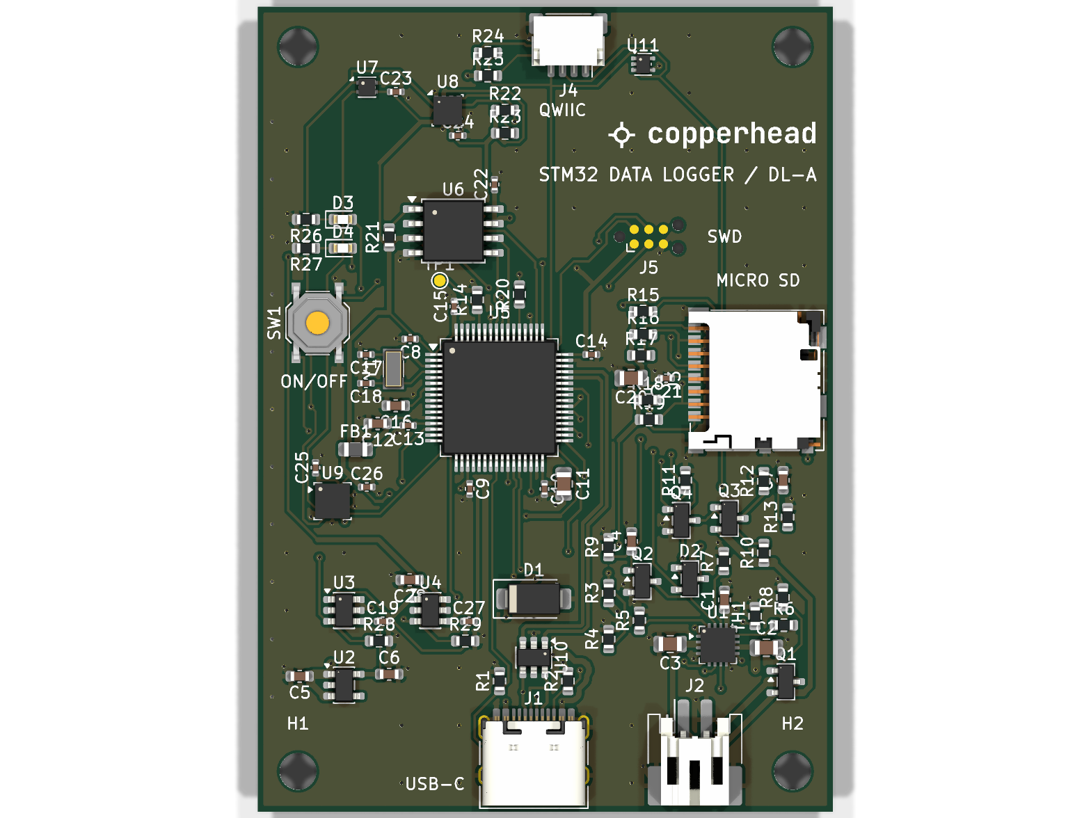
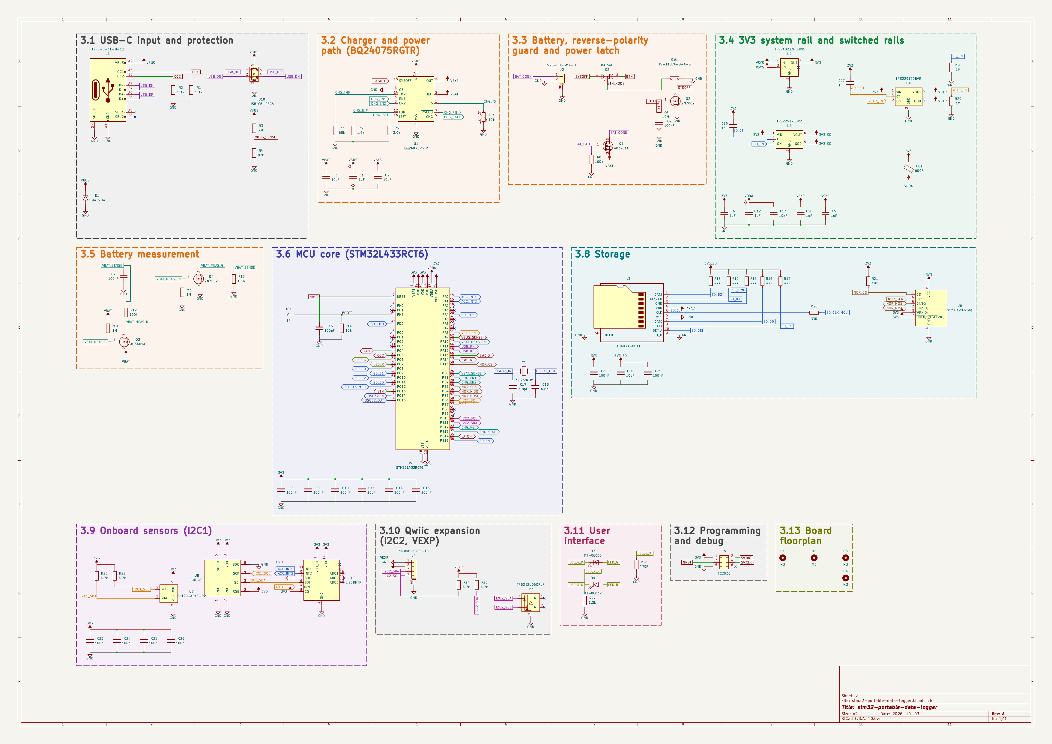
The design documents are in docs/:
SPEC.md: the specification.SUBSYSTEMS.md: the circuit, block by block.PINOUT.md: the MCU pin map.BOM.md: every part, with its reason.DECISIONS.md: the design's decisions.From docs/BOARD-STATS.md:
The custom design rules are in hardware/stm32-portable-data-logger.kicad_dru:
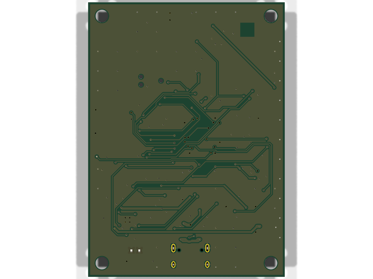
hardware/   KiCad project: schematic, board, design rules, vendored symbol library
docs/       design documents, board statistics, schematic as PDF and SVG
fab/        gerbers, drill, BOM and CPL (read the warning in that folder)
images/     renders of the board, not photographs
3d/         STEP, GLB and STL models
LICENSES/ full text of the licences belowOpen: use KiCad 10.0.4 or later on hardware/stm32-portable-data-logger.kicad_pro.
The schematic's symbols are vendored in hardware/sym-lib-cache/ (through sym-lib-table),
so it opens without extra libraries.
Fab files: read fab/2026-10-04-UNVERIFIED/README.md
first. It says how the files were made, which changes were made to the generated output (the
two inner layers were added), and what has not been checked.
Before ordering anything:
3D models: KiCad's 3D library has no model for six of the footprints (J1, J2, J3, U1, U7, SW1).
images/ shows close stand-ins from the same library: a GCT USB4105
for J1, a JST PH-K for J2, a Hirose DM3D for J3, WQFN-16 for U1, WSON-6 for U7, a TL3342 for
SW1.3d/ is exported from hardware/ as it is, so those six parts have no
body there.Use the models for fit, not tolerance.
| What | Licence |
|---|---|
Hardware: everything under hardware/, fab/ and 3d/ | CERN-OHL-S-2.0 (strongly reciprocal) |
Documentation and images: docs/, images/, README.md | CC-BY-4.0 |
Full texts are in LICENSES/. See LICENSE for the per-directory
statement.
Trademarks are not licensed. The copperhead mark on the silkscreen is a trademark; the licences above cover the design, not the mark. If you fabricate a modified board, remove it.
No warranty. CERN-OHL-S-2.0 sections 8 and 9 apply: no warranty, no liability.
| Qty | Value | Footprint | References |
|---|---|---|---|
| 11 | 100nF | Capacitor_SMD:C_0402_1005Metric | C8, C9, C10, C14, C15, C21, C22, C23, C24, C25, C26 |
| 5 | 1uF | Capacitor_SMD:C_0603_1608Metric | C1, C5, C6, C12, C28 |
| 5 | 47k | Resistor_SMD:R_0603_1608Metric | R15, R16, R17, R18, R19 |
| 4 | 10uF | Capacitor_SMD:C_0805_2012Metric | C2, C3, C11, C20 |
| 4 | 1M | Resistor_SMD:R_0603_1608Metric | R10, R11, R28, R29 |
| 4 | 4.7k | Resistor_SMD:R_0603_1608Metric | R22, R23, R24, R25 |
| 4 | M3 | MountingHole:MountingHole_3.2mm_M3 | H1, H2, H3, H4 |
| 3 | 100k | Resistor_SMD:R_0603_1608Metric | R8, R12, R13 |
| 3 | 100nF | Capacitor_SMD:C_0603_1608Metric | C4, C7, C16 |
| 3 | 10k | Resistor_SMD:R_0603_1608Metric | R14, R21, TH1 |
| 2 | 1nF | Capacitor_SMD:C_0402_1005Metric | C19, C27 |
| 2 | 2N7002 | Package_TO_SOT_SMD:SOT-23 | Q2, Q4 |
| 2 | 5.1k | Resistor_SMD:R_0603_1608Metric | R1, R2 |
| 2 | 6.8pF | Capacitor_SMD:C_0402_1005Metric | C17, C18 |
| 2 | AO3401A | Package_TO_SOT_SMD:SOT-23 | Q1, Q3 |
| 2 | TPS22917DBVR | Package_TO_SOT_SMD:SOT-23-6 | U3, U4 |
| 1 | 1.2k | Resistor_SMD:R_0603_1608Metric | R27 |
| 1 | 1.6k | Resistor_SMD:R_0603_1608Metric | R6 |
| 1 | 104031-0811 | Connector_Card:microSD_HC_Molex_104031-0811 | J3 |
| 1 | 10M | Resistor_SMD:R_0603_1608Metric | R9 |
| 1 | 10nF | Capacitor_SMD:C_0402_1005Metric | C13 |
| 1 | 3.0k | Resistor_SMD:R_0603_1608Metric | R5 |
| 1 | 32.768kHz | Crystal:Crystal_SMD_3215-2Pin_3.2x1.5mm | Y1 |
| 1 | 33R | Resistor_SMD:R_0603_1608Metric | R20 |
| 1 | 33k | Resistor_SMD:R_0603_1608Metric | R3 |
| 1 | 470R | Resistor_SMD:R_0603_1608Metric | R26 |
| 1 | 600R | Inductor_SMD:L_0805_2012Metric | FB1 |
| 1 | 68k | Resistor_SMD:R_0603_1608Metric | R7 |
| 1 | 82k | Resistor_SMD:R_0603_1608Metric | R4 |
| 1 | BAT54C | Package_TO_SOT_SMD:SOT-23 | D2 |
| 1 | BME280 | Package_LGA:Bosch_LGA-8_2.5x2.5mm_P0.65mm_ClockwisePinNumbering | U8 |
| 1 | BQ24075RGTR | Package_DFN_QFN:VQFN-16-1EP_3x3mm_P0.5mm_EP1.68x1.68mm | U1 |
| 1 | KT-0603G | LED_SMD:LED_0603_1608Metric | D3 |
| 1 | KT-0603R | LED_SMD:LED_0603_1608Metric | D4 |
| 1 | LIS3DHTR | Package_LGA:LGA-16_3x3mm_P0.5mm_LayoutBorder3x5y | U9 |
| 1 | S2B-PH-SM4-TB | Connector_JST:JST_PH_S2B-PH-SM4-TB_1x02-1MP_P2.00mm_Horizontal | J2 |
| 1 | SHT40-AD1F-R2 | Sensor_Humidity:Sensirion_DFN-4_1.5x1.5mm_P0.8mm_SHT4x_NoCentralPad | U7 |
| 1 | SM04B-SRSS-TB | Connector_JST:JST_SH_SM04B-SRSS-TB_1x04-1MP_P1.00mm_Horizontal | J4 |
| 1 | SMAJ6.0A | Diode_SMD:D_SMA | D1 |
| 1 | STM32L433RCT6 | Package_QFP:LQFP-64_10x10mm_P0.5mm | U5 |
| 1 | TC2030 | Connector:Tag-Connect_TC2030-IDC-NL_2x03_P1.27mm_Vertical | J5 |
| 1 | TP | TestPoint:TestPoint_Pad_D1.0mm | TP1 |
| 1 | TPD2E2U06DRLR | Package_TO_SOT_SMD:SOT-553 | U11 |
| 1 | TPS7A0233PDBVR | Package_TO_SOT_SMD:SOT-23-5 | U2 |
| 1 | TS-1187A-B-A-B | Button_Switch_SMD:SW_Push_1P1T_XKB_TS-1187A | SW1 |
| 1 | TYPE-C-31-M-12 | Connector_USB:USB_C_Receptacle_HRO_TYPE-C-31-M-12 | J1 |
| 1 | USBLC6-2SC6 | Package_TO_SOT_SMD:SOT-23-6 | U10 |
| 1 | W25Q128JVSIQ | Package_SO:SOIC-8_5.3x5.3mm_P1.27mm | U6 |
andrewsharmon/rp2350-stepper-controller
Low-cost 10-axis sine-microstepping controller for small steppers on the RP2350 (PIO + DMA). WIP.

naturalhazardscience/groundlark
Open source hardware for community-powered citizen science

embeddedos-org/eCAD-Hardware-Products
Hardware designs + EE docs + Board datasheets of Multiple products


vaknin/PCB
Hardware ideas to fab-ready PCBs as code: Rust pcbgen on KiCad 10, Freerouting, ESP-IDF firmware with QEMU/Wokwi simulation, CadQuery enclosures

FujiNetWIFI/fujinet-hardware
Schematics and design files for FujiNet hardware

CappyT/freedo
Local coordinator for tado V3+ heating devices, with a Home Assistant integration and add-on

nikolaus018/garageDoor-pro
ESP32-C3 + GPS board that opens the garage door when you leave and arrive: firmware, KiCad PCB and perfboard build
It measures 50 × 70 mm and has 4 copper layers, 1.6 mm thick.
90 parts, built around the STM32L433RCT6, BME280, SHT40-AD1F-R2 and W25Q128JVSIQ. The full list of its parts is on this page, with links to each part's symbol and footprint where PCBKit's library has them.
From the copperheadhq/copperhead-stm32-data-logger repository on GitHub, at the commit this page was made from: the board is hardware/stm32-portable-data-logger.kicad_pcb and its schematic hardware/stm32-portable-data-logger.kicad_sch. PCBKit opens the board in the browser, with nothing to install.
Its repository states no licence, so its author keeps all rights: ask copperheadhq before reusing the design.