4 layers82 × 100 mm
Falcon Edge
rmingon/Falcon-Edge
A 3D-printable flying-wing airframe with a custom ESP32 flight computer—open hardware you can solder, screw together, and fly.
48 parts11

 rmingon/Falcon-Edge11
A 3D-printable flying-wing airframe with a custom ESP32 flight computer—open hardware you can solder, screw together, and fly.
Hardware v2 is an open-source printed circuit board by rmingon, from the rmingon/Falcon-Edge repository on GitHub. It is a 2-layer board of 40 × 78 mm with 56 parts on 140 nets.
It is built around the CH340C, ESP32-WROOM-32 and BMP280, with the TPS562200DDC, BMI160 and RFM95W-868S2 among its other parts. Its parts include 17 capacitors, 15 resistors, 8 connectors, 7 ICs and 3 diodes. It belongs with the ESP32 boards of this library.


This repository contains hardware designs, documentation, and code for an aircraft project.
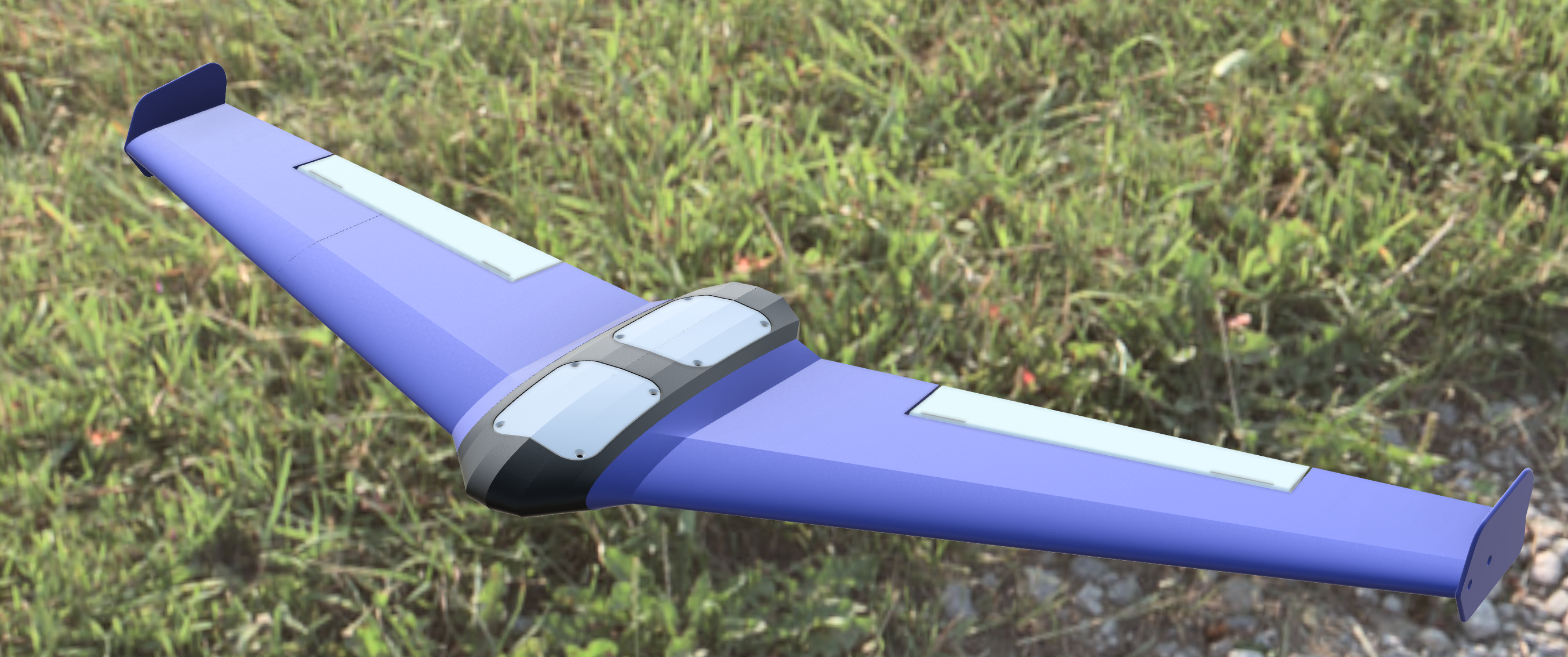
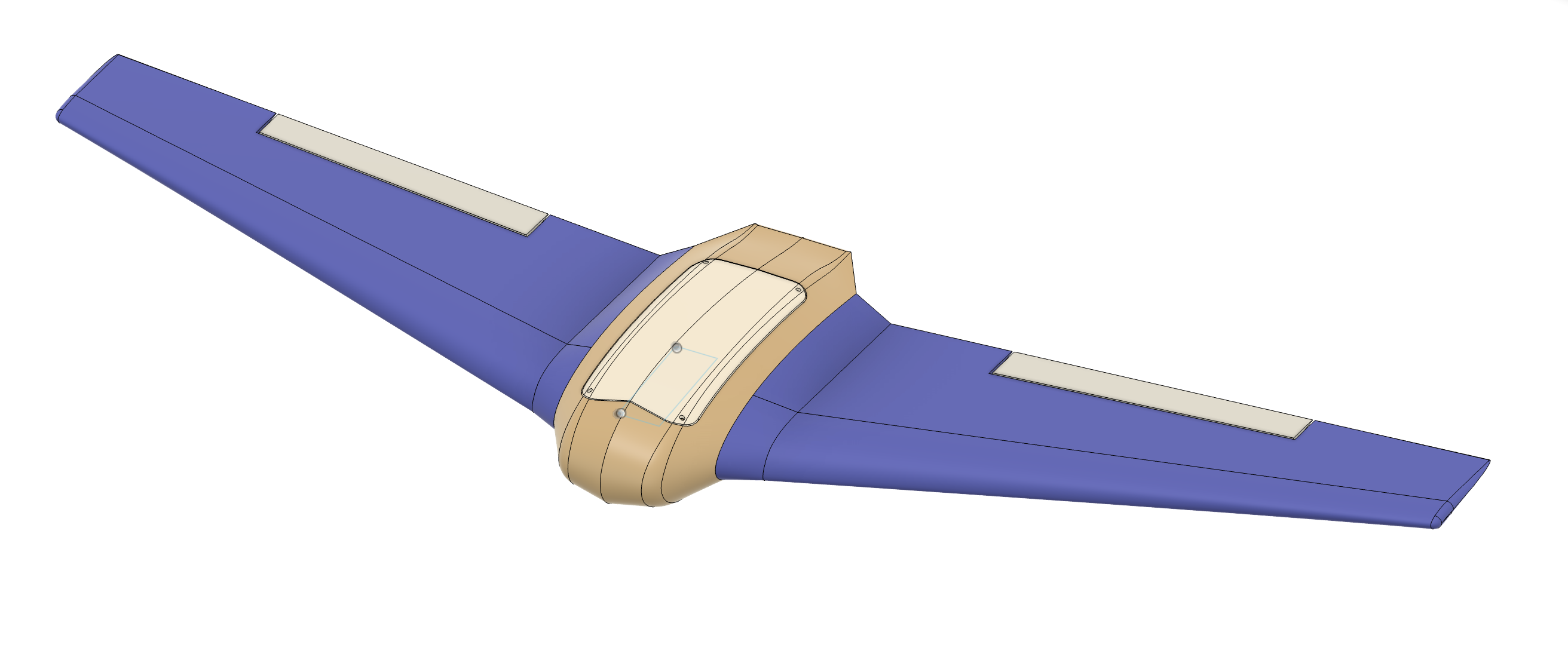
Falcon-Edge is a compact flying-wing airframe with a custom ESP32-based flight computer.
This repo contains the KiCad hardware project and 3D CAD needed to print, assemble, and fly your own Falcon-Edge.
Airframe
Avionics (KiCad)
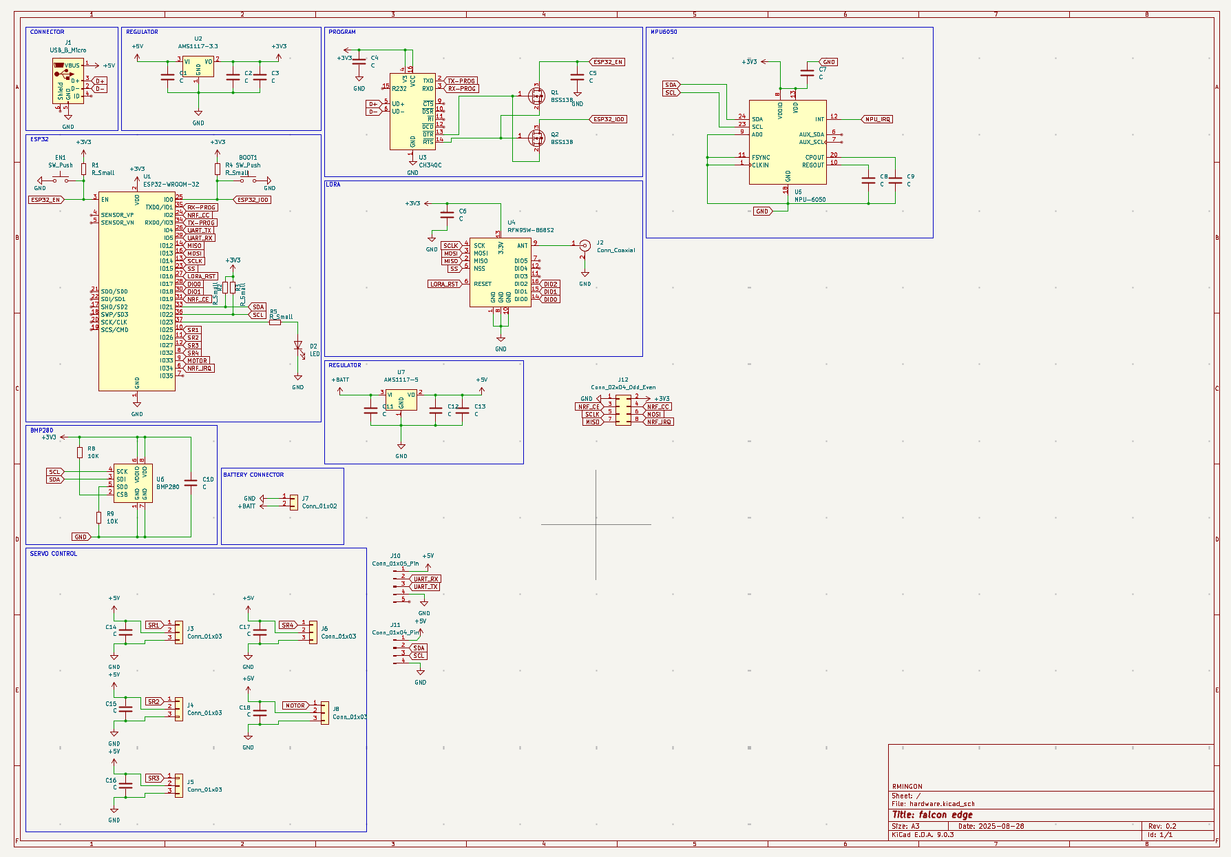
See the schematic for exact pin mapping and connector naming.
hardware/ # KiCad project (.kicad_pro, .kicad_pcb, .kicad_sch, etc.) cad/ # 3D parts for the center pod, hatches, and mounting (STLs/STEP) images/ # Renders and board views used in this README (optional)
(If you keep everything at the repo root, this README references the images there by filename.)
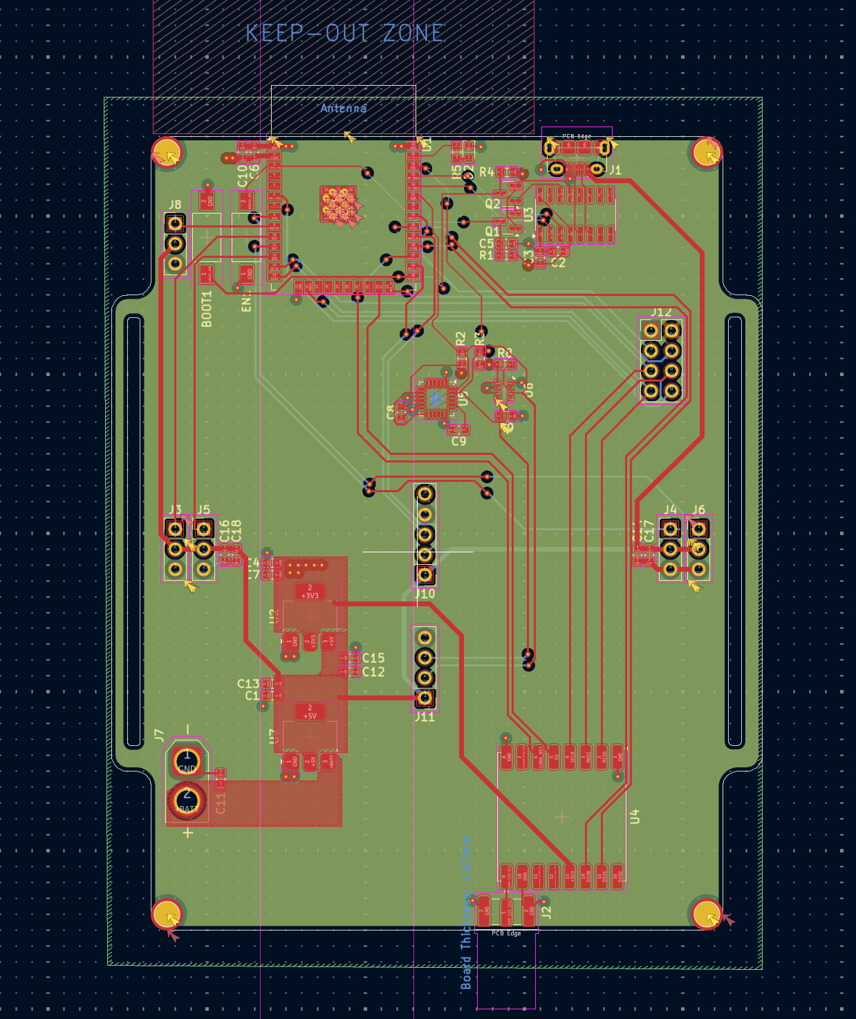
hardware.kicad_pro – projecthardware.kicad_sch – schematichardware.kicad_pcb – PCB layoutBoard preview
Schematic overview
Top hatch opening
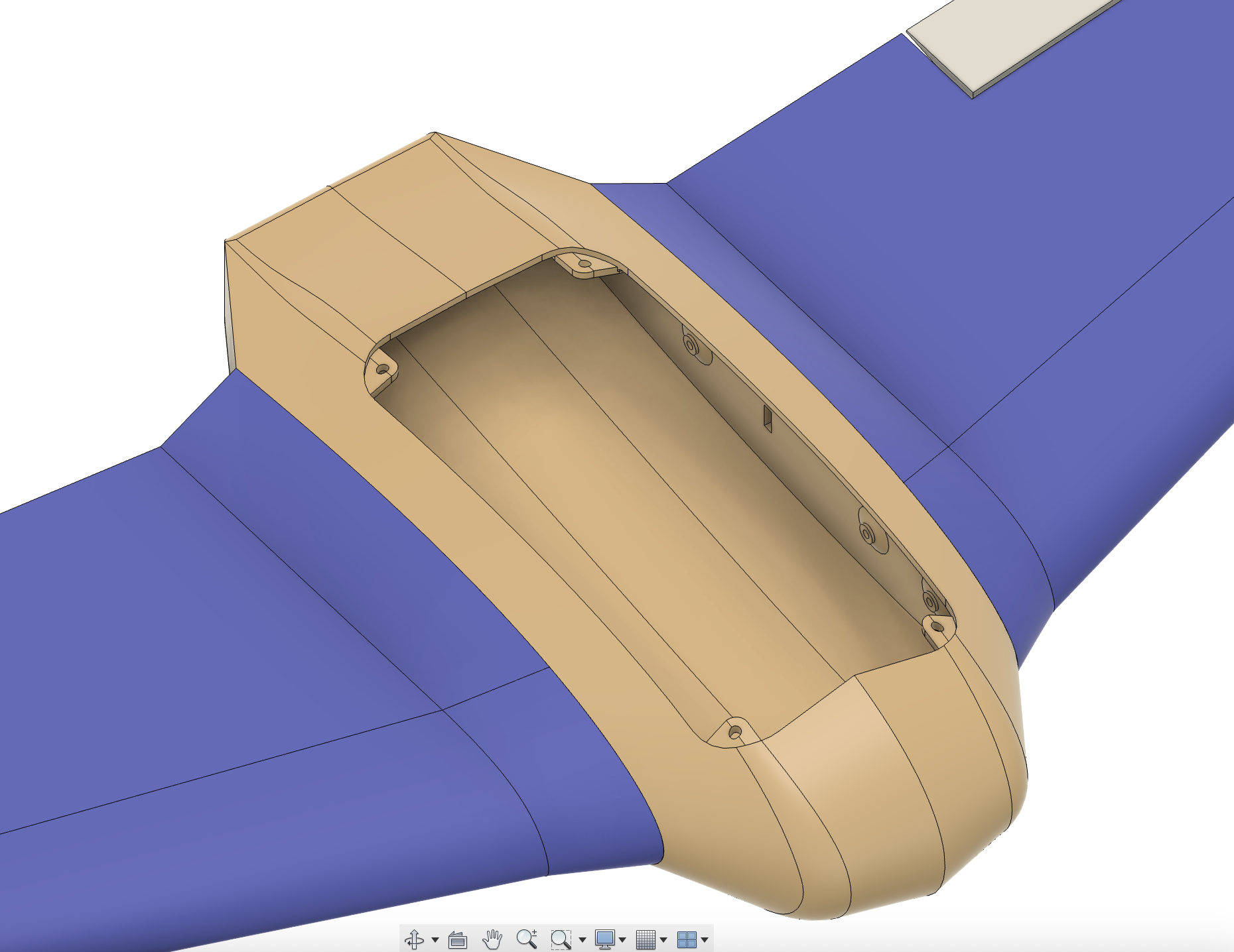
Bottom hatch opening
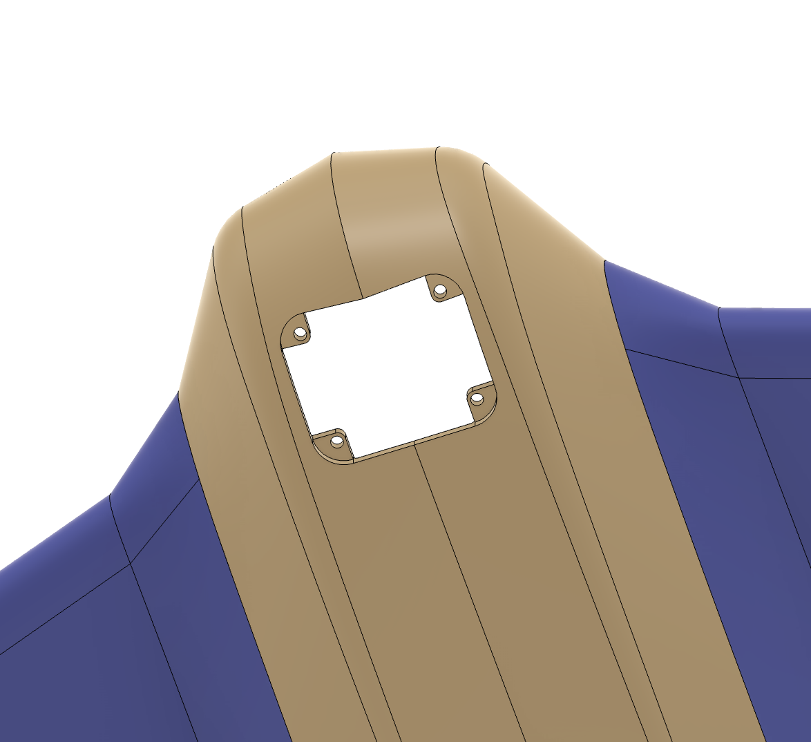
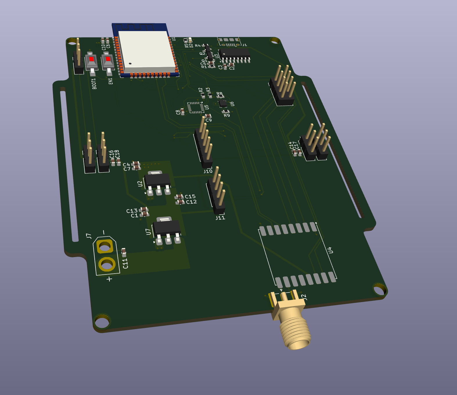
Exact connector names/positions: see the KiCad schematic & silkscreen.
3D view of the board
Airframe with pod & hatches
PRs and issues are welcome:
LICENSE-hardware)LICENSE-docs)LICENSE-code)If you use, modify, or redistribute any part of this project, you must give credit as follows:
Based on FalconEgde by Rmingon (https://github.com/rmingon/Falcon-Edge) — Licensed under the corresponding license.
See NOTICE for full details.
Designed and built by RMINGON.
| Qty | Value | Footprint | References |
|---|---|---|---|
| 11 | C | Capacitor_SMD:C_0603_1608Metric | C1, C2, C3, C6, C8, C10, C11, C12, C14, C15, C18 |
| 4 | 10K | Resistor_SMD:R_0603_1608Metric | R8, R9, R11, R13 |
| 3 | 1.1K | Resistor_SMD:R_0603_1608Metric | R7, R10, R40 |
| 3 | 100nF | Capacitor_SMD:C_0603_1608Metric | C16, C17, C19 |
| 3 | Conn_01x03 | Connector_PinHeader_2.54mm:PinHeader_1x03_P2.54mm_Vertical | J3, J4, J8 |
| 3 | LED | LED_SMD:LED_0603_1608Metric | D1, D2, D8 |
| 3 | R_Small | Resistor_SMD:R_0603_1608Metric | R1, R4, R5 |
| 2 | 0.1µF | Capacitor_SMD:C_0603_1608Metric | C7, C9 |
| 2 | 4.7k | Resistor_SMD:R_0603_1608Metric | R2, R3 |
| 2 | 4.7uH | Inductor_SMD:L_Chilisin_BMRA00050520 | L1, L2 |
| 2 | Conn_01x06 | Connector_JST:JST_SH_BM06B-SRSS-TB_1x06-1MP_P1.00mm_Vertical | J1, J5 |
| 2 | SW_Push | Button_Switch_SMD:SW_SPST_FSMSM | BOOT1, EN1 |
| 2 | TPS562200 | Package_TO_SOT_SMD:SOT-23-6 | U2, U5 |
| 2 | TestPoint | TestPoint:TestPoint_Pad_3.0x3.0mm | TP1, TP2 |
| 1 | 10nF | Capacitor_SMD:C_0603_1608Metric | C20 |
| 1 | 33.0K | Resistor_SMD:R_0603_1608Metric | R14 |
| 1 | 500 | Resistor_SMD:R_0603_1608Metric | R6 |
| 1 | 54.9K | Resistor_SMD:R_0603_1608Metric | R12 |
| 1 | BMI160 | bmi160:PQFN50P250X300X88-14N | U9 |
| 1 | BMP280 | Package_LGA:Bosch_LGA-8_2x2.5mm_P0.65mm_ClockwisePinNumbering | U6 |
| 1 | CH340C | Package_SO:SOIC-16_3.9x9.9mm_P1.27mm | U8 |
| 1 | Conn_Coaxial | Connector_Coaxial:SMA_Samtec_SMA-J-P-H-ST-EM1_EdgeMount | J2 |
| 1 | ESP32-WROOM-32 | RF_Module:ESP32-WROOM-32 | U1 |
| 1 | MDT320B03001 | MDT320B03001:AMPHENOL_MDT320B03001 | J6 |
| 1 | RFM95W-868S2 | RF_Module:HOPERF_RFM9XW_SMD | U4 |
| 1 | USB_C_Plug | Connector_USB:USB_C_Receptacle_GCT_USB4105-xx-A_16P_TopMnt_Horizontal | P1 |
rmingon/Falcon-Edge
A 3D-printable flying-wing airframe with a custom ESP32 flight computer—open hardware you can solder, screw together, and fly.

rmingon/Falcon-Edge
A 3D-printable flying-wing airframe with a custom ESP32 flight computer—open hardware you can solder, screw together, and fly.

rmingon/Falcon-Edge
A 3D-printable flying-wing airframe with a custom ESP32 flight computer—open hardware you can solder, screw together, and fly.


fredszaq/crossometer-mini
Design files for crossometer-mini device


It measures 40 × 78 mm and has 2 copper layers, 1.6 mm thick.
56 parts, built around the CH340C, ESP32-WROOM-32, BMP280 and TPS562200DDC. The full list of its parts is on this page, with links to each part's symbol and footprint where PCBKit's library has them.
From the rmingon/Falcon-Edge repository on GitHub, at the commit this page was made from: the board is hardware-v2/hardware-v2.kicad_pcb and its schematic camera-stabilization_hardware/camera-stabilization_hardware.kicad_sch. PCBKit opens the board in the browser, with nothing to install.
Its repository states no licence, so its author keeps all rights: ask rmingon before reusing the design.