2 layers43.2 × 17.8 mm

 rkhvrnen/UDS-logger
A Python script and MCU source code for collecting real-time diagnostic data from control units of a vehicle using UDS over CAN bus.
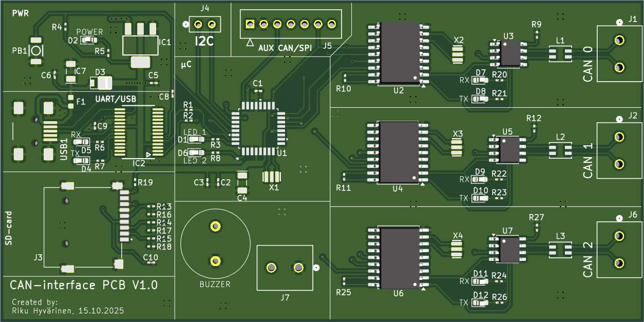
CAN interface is an open-source printed circuit board by rkhvrnen, from the rkhvrnen/UDS-logger repository on GitHub, published under the MIT licence. It is a 2-layer board of 120 × 60 mm with 82 parts on 124 nets, routed with 596 tracks and 190 vias.
It is built around the MCP2551-I/SN-HG, FT232RL and LM1117IMPX-5.0, with the M20-9990246, ACT1210-101-2P-TL00 and MF-FSMF050X-2 among its other parts. Its parts include 30 resistors, 12 diodes, 10 capacitors, 10 connectors and 9 ICs. It belongs with the interfaces and adapters boards of this library.


PCB V1.0
| Qty | Value | Footprint | References |
|---|---|---|---|
| 14 | 1K | Resistor_SMD:R_0603_1608Metric_Pad0.98x0.95mm_HandSolder | R1, R2, R3, R4, R5, R6, R7, R8, R20, R21, R22, R23, R24, R26 |
| 5 | 100n | Capacitor_SMD:C_0603_1608Metric_Pad1.08x0.95mm_HandSolder | C1, C6, C8, C9, C10 |
| 4 | 10K | Resistor_SMD:R_0603_1608Metric_Pad0.98x0.95mm_HandSolder | R10, R11, R19, R25 |
| 4 | 16MHz | NanoV3.3:RESONATOR | X1, X2, X3, X4 |
| 4 | 1729128 | 1729128:CONN_1729128_PXC | J1, J2, J6, J7 |
| 4 | M20-9990246 | M20-9990246:CONN2_M20-999_1x2_HRW | J4, J8, J9, J10 |
| 3 | 1.8K | Resistor_SMD:R_0603_1608Metric_Pad0.98x0.95mm_HandSolder | R13, R14, R15 |
| 3 | 120 | Resistor_SMD:R_0603_1608Metric_Pad0.98x0.95mm_HandSolder | R28, R29, R30 |
| 3 | 1u | Capacitor_SMD:C_0603_1608Metric_Pad1.08x0.95mm_HandSolder | C2, C3, C5 |
| 3 | 3.3K | Resistor_SMD:R_0603_1608Metric_Pad0.98x0.95mm_HandSolder | R16, R17, R18 |
| 3 | 47K | Resistor_SMD:R_0603_1608Metric_Pad0.98x0.95mm_HandSolder | R9, R12, R27 |
| 3 | ACT1210-101-2P-TL00 | ACT1210:IND_01-2P-TL00_TDK | L1, L2, L3 |
| 3 | MCP2515-xSO | Package_SO:SOIC-18W_7.5x11.6mm_P1.27mm | U2, U4, U6 |
| 3 | MCP2551-I-SN | Package_SO:SOIC-8_3.9x4.9mm_P1.27mm | U3, U5, U7 |
| 2 | 4.7u | NanoV3.3:TAN-A | C4, C7 |
| 2 | LED | LED_SMD:LED_0603_1608Metric_Pad1.05x0.95mm_HandSolder | D1, D6 |
| 2 | LED_RX_CAN1 | LED_SMD:LED_0603_1608Metric_Pad1.05x0.95mm_HandSolder | D9, D11 |
| 2 | LED_TX_CAN1 | LED_SMD:LED_0603_1608Metric_Pad1.05x0.95mm_HandSolder | D10, D12 |
| 1 | 328P-MUR | ATMEGA328P:TQFP32_32A_MCH | U1 |
| 1 | FT232RL | NanoV3.3:SSOP28 | IC2 |
| 1 | LED_PWR | LED_SMD:LED_0603_1608Metric_Pad1.05x0.95mm_HandSolder | D2 |
| 1 | LED_RX (Red) | LED_SMD:LED_0603_1608Metric_Pad1.05x0.95mm_HandSolder | D4 |
| 1 | LED_RX_CAN0 | LED_SMD:LED_0603_1608Metric_Pad1.05x0.95mm_HandSolder | D7 |
| 1 | LED_TX (Green) | LED_SMD:LED_0603_1608Metric_Pad1.05x0.95mm_HandSolder | D5 |
| 1 | LED_TX_CAN0 | LED_SMD:LED_0603_1608Metric_Pad1.05x0.95mm_HandSolder | D8 |
| 1 | LM1117IMPX-5.0 | NanoV3.3:LINEAR_SOT223 | IC1 |
| 1 | MFFSMF050 | NanoV3.3:0603-1608X90N | F1 |
| 1 | PPTC071LFBN-RC | PPTC071LFBN-RC:CONN_xPxC071LFBN-RC_SUL | J5 |
| 1 | SD-card | MSD-1-A:CUI_MSD-1-A | J3 |
| 1 | SS1P3L | NanoV3.3:DO220AAL | D3 |
| 1 | ~ | NanoV3.3:USB-MINI-B_2 | USB1 |
| 1 | ~ | Buzzer:Buzzer | BZ1 |
| 1 | ~ | NanoV3.3:SMD_157SW | PB1 |

javachaos/arduino_simulator
arduinosimulator is a standalone AVR simulation and board-tooling workspace.


FinnKrieger/dashbox-pcb
A two-layer dashboard controller board for the USC Formula Electric car. It sits on the vehicle CAN bus, drives the driver-facing dash, and takes its power from the car's 12 V rail.

It measures 120 × 60 mm and has 2 copper layers, 1.6 mm thick.
82 parts, built around the MCP2551-I/SN-HG, FT232RL, LM1117IMPX-5.0 and M20-9990246. The full list of its parts is on this page, with links to each part's symbol and footprint where PCBKit's library has them.
From the rkhvrnen/UDS-logger repository on GitHub, at the commit this page was made from: the board is pcb/CAN_interface.kicad_pcb and its schematic pcb/CAN_interface.kicad_sch. PCBKit opens the board in the browser, with nothing to install.
Its repository publishes it under the MIT licence: you may reuse it on that licence's terms (keep the author's notice, and for a copyleft licence share your changes alike).