2 layers157.5 × 67.3 mm

 ricaflops/Jupiter-II43
Another Jupiter Ace computer clone
Jupiter II is an open-source printed circuit board by ricaflops, from the ricaflops/Jupiter-II repository on GitHub, published under the MIT licence. It is a 2-layer board of 164.5 × 89.5 mm with 126 parts on 162 nets, routed with 2,501 tracks and 167 vias.
It is built around the 74LS367PC, 27C128-15 and 74HC4040D, with the 74LS166AP-E, L7805 and BC817 among its other parts. Its parts include 58 resistors, 23 capacitors, 17 ICs, 11 diodes and 6 connectors. It belongs with the retro computing and games boards and the FPGA and CPLD boards of this library.


Another Jupiter Ace computer clone
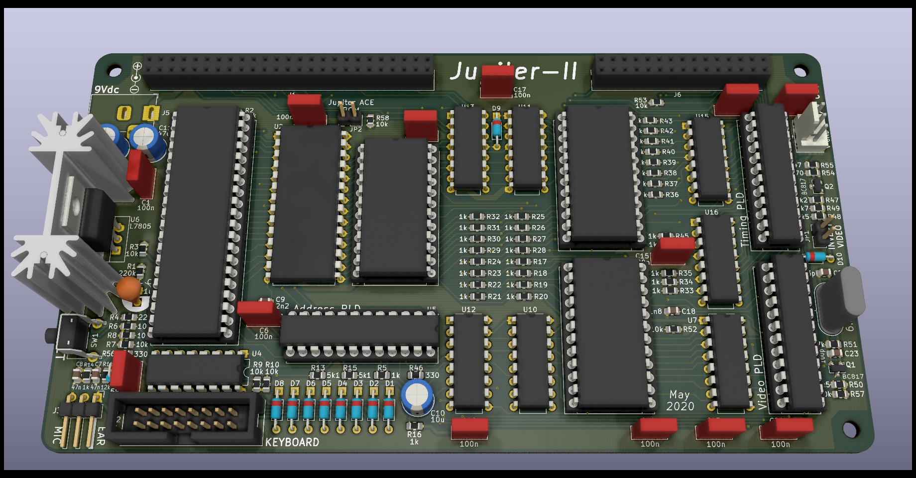
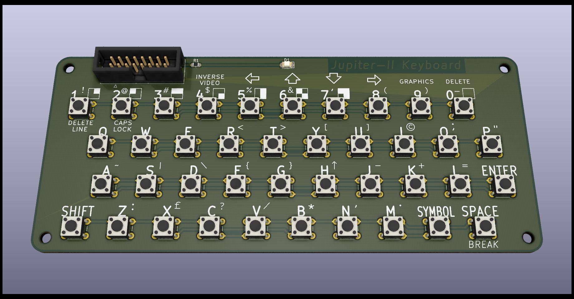
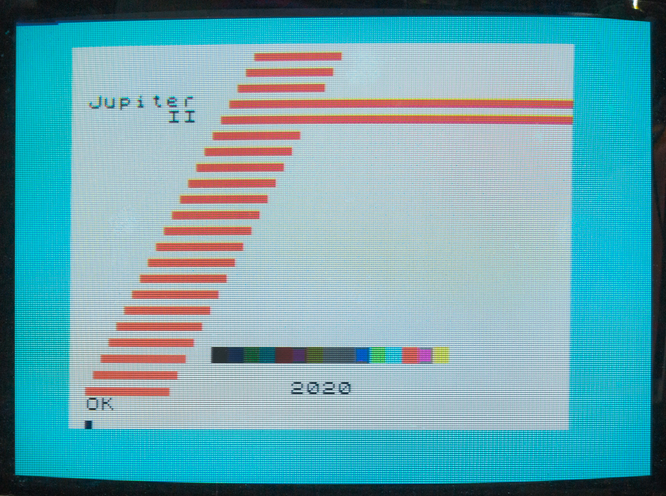
For more information on the original Jupiter Ace computer and an extensive software collection visit The Jupiter Ace Archive
See the Jupiter-II Expansion project for adding:
Inverse Video Jumper
ROM image selection Jumper
The original Jupiter Ace 8K ROM image can be found at The Jupiter Ace Archive.
Connect a 7.5Vdc to 9 Vdc x 1A power supply. Center pin is positive.
The video standard is 60Hz NTSC compatible but converting to 50Hz PAL by recoding the PLDs shall not be too difficult.
50 pin header connector (2x25 female). Similar layout as the original Jupiter Ace with additional pins "-ROMSL" and "SPEAKER"
(n.c.) means not connected
-ROMSL (in) Disables internal ROM chip when connected to +5V
SPEAKER (out) TTL level Speaker signal (BEEP)
30 pins header connector (2x15 female). Similar layout as the original Jupiter Ace with some additional pins.
-VRAMWR (out) Video RAM write enable
-CPAGE (in) Character Generator page selection
-SPAGE (in) Screen page selection
-SCRRAM (out) Screen RAM enabled
-VSYNC (out) Vertical Video Synch
-HSYNC (out) Horizontal Video Synch
LUMA (out) Video Luminance
BLANK (out) Video Blanking (retrace blanking)
| Qty | Value | Footprint | References |
|---|---|---|---|
| 33 | 1k | Resistor_SMD:R_0805_2012Metric_Pad1.15x1.40mm_HandSolder | R12, R14, R16, R17, R18, R19, R20, R21, R22, R23, R24, R25, R26, R27, R28, R29 +17 |
| 13 | 100n | Capacitors_THT:C_Rect_L7.0mm_W2.5mm_P5.00mm | C1, C2, C3, C5, C6, C13, C14, C15, C16, C17, C20, C24, C25 |
| 11 | 10k | Resistor_SMD:R_0805_2012Metric_Pad1.15x1.40mm_HandSolder | R2, R3, R6, R7, R8, R9, R10, R52, R53, R57, R58 |
| 10 | 1N914 | Diodes_THT:D_DO-35_SOD27_P7.62mm_Horizontal | D1, D2, D3, D4, D5, D6, D7, D8, D9, D10 |
| 5 | 74LS367 | Housings_DIP:DIP-16_W7.62mm | U4, U10, U11, U12, U13 |
| 3 | 6116 | Housings_DIP:DIP-24_W15.24mm_Socket | U1, U8, U9 |
| 3 | GAL22V10 | Housings_DIP:DIP-24_W7.62mm_Socket | U5, U14, U17 |
| 3 | MountingHole | Mounting_Holes:MountingHole_3.2mm_M3 | H1, H2, H3 |
| 2 | 10u | Capacitors_THT:CP_Radial_D6.3mm_P2.50mm | C10, C12 |
| 2 | 1k5 | Resistor_SMD:R_0805_2012Metric_Pad1.15x1.40mm_HandSolder | R48, R50 |
| 2 | 330 | Resistor_SMD:R_0805_2012Metric_Pad1.15x1.40mm_HandSolder | R46, R56 |
| 2 | 47n | Capacitor_SMD:C_0805_2012Metric_Pad1.15x1.40mm_HandSolder | C7, C8 |
| 2 | 5k1 | Resistor_SMD:R_0805_2012Metric_Pad1.15x1.40mm_HandSolder | R13, R15 |
| 2 | 74HC4040 | Housings_DIP:DIP-16_W7.62mm | U15, U16 |
| 2 | BC817 | TO_SOT_Packages_SMD:SOT-23 | Q1, Q2 |
| 1 | 100p | Capacitor_SMD:C_0805_2012Metric_Pad1.15x1.40mm_HandSolder | C23 |
| 1 | 12k | Resistor_SMD:R_0805_2012Metric_Pad1.15x1.40mm_HandSolder | R11 |
| 1 | 1n8 | Capacitor_SMD:C_0805_2012Metric_Pad1.15x1.40mm_HandSolder | C18 |
| 1 | 1u | Capacitors_THT:CP_Radial_D6.3mm_P2.50mm | C4 |
| 1 | 220 | Resistor_SMD:R_0805_2012Metric_Pad1.15x1.40mm_HandSolder | R4 |
| 1 | 220k | Resistor_SMD:R_0805_2012Metric_Pad1.15x1.40mm_HandSolder | R1 |
| 1 | 27C128 | Package_DIP:DIP-28_W15.24mm | U2 |
| 1 | 2k2 | Resistor_SMD:R_0805_2012Metric_Pad1.15x1.40mm_HandSolder | R47 |
| 1 | 2k7 | Resistor_SMD:R_0805_2012Metric_Pad1.15x1.40mm_HandSolder | R49 |
| 1 | 2n2 | Capacitor_SMD:C_0805_2012Metric_Pad1.15x1.40mm_HandSolder | C9 |
| 1 | 33p | Capacitor_SMD:C_0805_2012Metric_Pad1.15x1.40mm_HandSolder | C22 |
| 1 | 47 | Resistor_SMD:R_0805_2012Metric_Pad1.15x1.40mm_HandSolder | R55 |
| 1 | 470 | Resistor_SMD:R_0805_2012Metric_Pad1.15x1.40mm_HandSolder | R54 |
| 1 | 47k | Resistor_SMD:R_0805_2012Metric_Pad1.15x1.40mm_HandSolder | R51 |
| 1 | 47u | Capacitors_THT:CP_Radial_D6.3mm_P2.50mm | C11 |
| 1 | 5V1 | Diodes_THT:D_DO-35_SOD27_P2.54mm_Vertical_KathodeUp | D11 |
| 1 | 6.55 MHz | Crystals:Crystal_HC18-U_Vertical | Y1 |
| 1 | 74LS166 | Housings_DIP:DIP-16_W7.62mm | U7 |
| 1 | 9Vdc | Connector_BarrelJack:BarrelJack_Horizontal | J5 |
| 1 | Conn_01x03 | Pin_Headers:Pin_Header_Angled_1x03_Pitch2.54mm | J3 |
| 1 | Conn_01x03 | Connectors_Molex:Molex_KK-6410-03_03x2.54mm_Straight | J4 |
| 1 | Conn_02x15_Odd_Even | Socket_Strips:Socket_Strip_Straight_2x15_Pitch2.54mm | J6 |
| 1 | EXPANSION | Socket_Strips:Socket_Strip_Straight_2x25_Pitch2.54mm | J1 |
| 1 | Heatsink | Jupiter Ace:Heatsink_35x12mm_2xFixation1.5mm | HS1 |
| 1 | Jumper | Connector_PinHeader_2.54mm:PinHeader_1x02_P2.54mm_Vertical | JP2 |
| 1 | Jumper | Pin_Headers:Pin_Header_Straight_1x02_Pitch2.54mm | JP1 |
| 1 | KEYBOARD | Connectors_Multicomp:Multicomp_MC9A12-1634_2x08x2.54mm_Straight | J2 |
| 1 | L7805 | TO_SOT_Packages_THT:TO-220-3_Vertical | U6 |
| 1 | SW_Push | Buttons_Switches_THT:SW_Tactile_SPST_Angled_PTS645Vx58-2LFS | SW1 |
| 1 | Symbol_Barrel_Polarity | Symbol:Symbol_Barrel_Polarity | REF01 |
| 1 | Z80CPU | Housings_DIP:DIP-40_W15.24mm_Socket | U3 |


RetroStack/TRS-80-Model-I-G-E1
Hardware Replica of the TRS-80 Model I Revision G

RetroStack/TRS-80-Model-I-Jap50-E1
Hardware Replica of the TRS-80 Model I Revision HE11E011550

RichCini/LomasBoards
Small repository of files/data related to Lomas Data Products S-100 boards.


ricaflops/Jupiter-II-Expansion
Expansion board for Jupiter-II computer

It measures 164.5 × 89.5 mm and has 2 copper layers, 1.6 mm thick.
126 parts, built around the 74LS367PC, 27C128-15, 74HC4040D and 74LS166AP-E. The full list of its parts is on this page, with links to each part's symbol and footprint where PCBKit's library has them.
From the ricaflops/Jupiter-II repository on GitHub, at the commit this page was made from: the board is Jupiter-II.kicad_pcb. PCBKit opens the board in the browser, with nothing to install.
Its repository publishes it under the MIT licence: you may reuse it on that licence's terms (keep the author's notice, and for a copyleft licence share your changes alike).