2 layers

 ricaflops/Jupiter-II-Expansion15
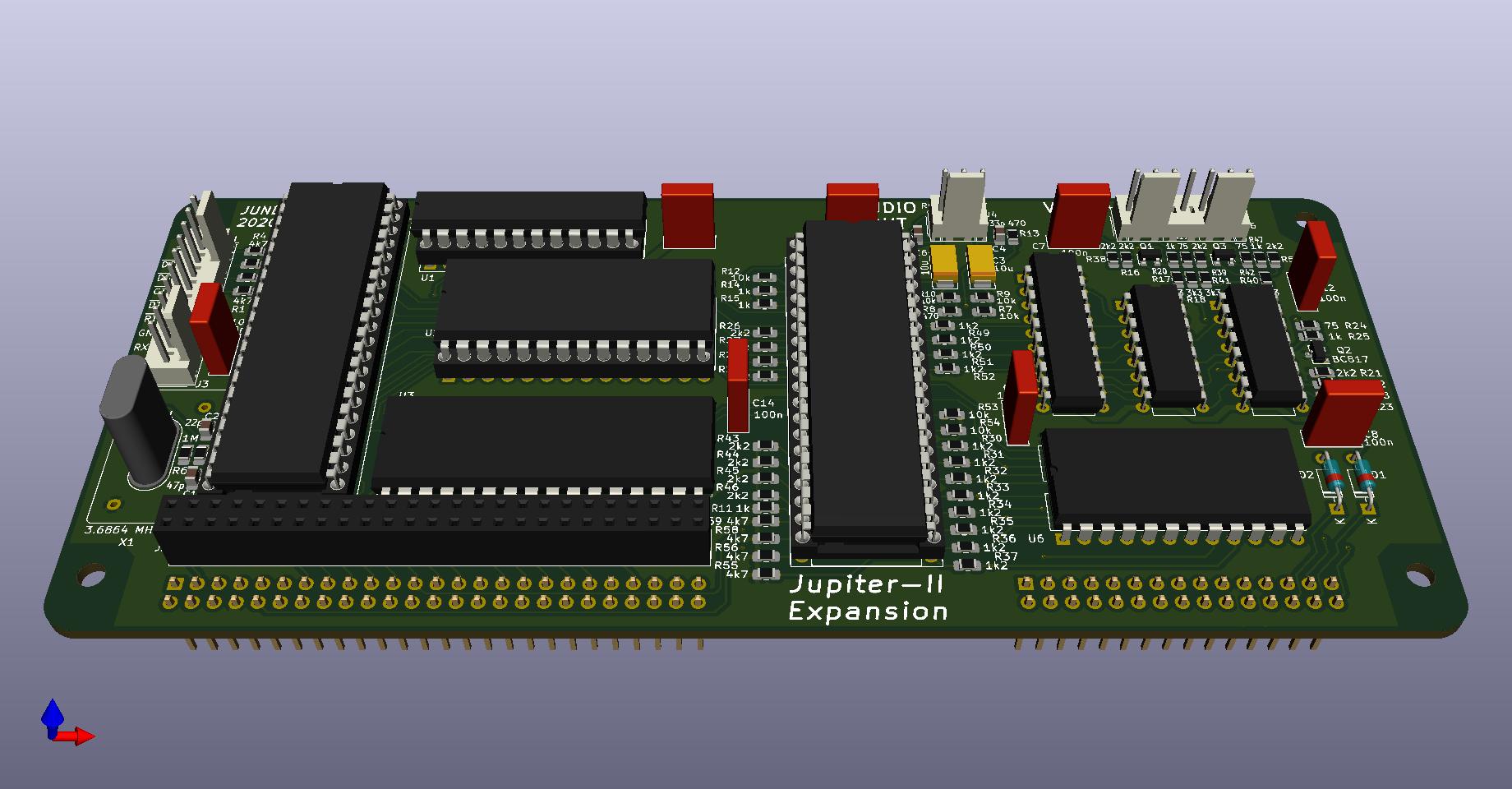
Expansion board for Jupiter-II computer
Jupiter II Expansion is an open-source printed circuit board by ricaflops, from the ricaflops/Jupiter-II-Expansion repository on GitHub, published under the MIT licence. It is a 2-layer board of 164.5 × 71.8 mm with 99 parts on 165 nets, routed with 1,423 tracks and 56 vias.
It is built around the 27C128-15, 74LS257PC and 74LS574N, with the BC817 among its other parts. Its parts include 59 resistors, 14 capacitors, 9 ICs, 6 connectors and 3 transistors. It belongs with the retro computing and games boards and the FPGA and CPLD boards of this library.


An Expansion board for the Jupiter-II computer
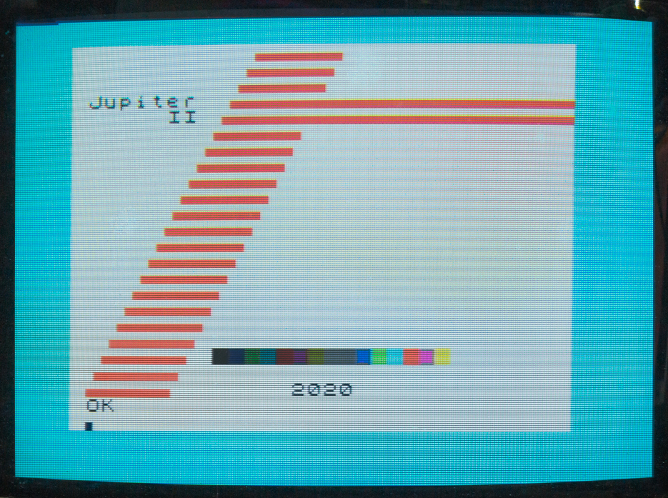
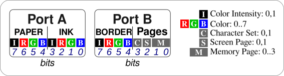
CYAN BORDER ( Change screen border color )
WHITE PAPER ( Set char background color )
BLUE DARK INK ( Set char foreground color )

: COLORBAR
  CLS 10 8 AT 16 0
  DO
   I INK 144 EMIT
  LOOP
  BLACK INK
  ;
COLORBAR ( Show a colorfull bar )0 FONT ( select alternative character set )
1 FONT ( select original character set )
0 SCREEN ( select screen page 0 )
1 SCREEN ( select screen page 1 )
0 MPAGE ( select memory page 0 )
3 MPAGE ( select memory page 3 ): PING
200 0 PSG!
254 7 PSG!
16 8 PSG!
20 12 PSG!
1 13 PSG!
;
: SHOT
8 6 PSG!
247 7 PSG!
16 8 PSG!
20 12 PSG!
1 13 PSG!
;8 data bits, 1 stop bit, no parity.
CREATE BUFFER 256 ALLOT ( Create and Allocate a memory space to work )
: CLRBUF BUFFER 256 32 FILL ; ( Clear Buffer )
: PRTBUF CR 256 0 DO BUFFER I + EMIT LOOP CR ; ( Print Buffer )

9600 BAUD     ( set communication baud rate )
CLRBUF        ( Clear Buffer )
BUFFER 256 RX ( Receive 256 bytes from serial line )
PRTBUF        ( View received data )
BUFFER 256 TX ( Transmit 256 bytes over serial line )
Note: use Space key to abort communication if needed
The extended vocabulary is copied from XROM to a unused 1K RAM area at $3000-$33FF of Jupiter-II during initialization. That allows safe memory paging while keeping the extra Words accessible.
COUNT ( addr -- addr+1 c )  Extract String length
+! ( n addr -- )  Add 'n' to 'addr' variable
? ( addr -- )  Print variable value
CMOVE ( addr1 addr2 n -- )  Copy 'n' bytes from 'addr1' to 'addr2'
FILL  ( addr n c -- )  Fill 'n' bytes with 'c' starting from 'addr'
DEPTH ( -- n )  Data Stack Depth
HEX ( -- ) Set numeric base to HexadecimalPSG! ( c reg -- ) Write 'c' to PSG register 'reg'
PSG@ ( reg -- c ) Read PSG register 'reg' contentsBORDER ( c -- ) Set screen BORDER to color 'c' , 0 to 15
INK ( c -- ) Set character INK to color 'c' , 0 to 15
PAPER ( c -- ) Set character PAPER to color 'c' , 0 to 15
BLACK ( -- c ) Stack color code for Black
GREY ( -- c ) Stack color code for Grey
BLUE ( -- c ) Stack color code for Blue
GREEN ( -- c ) Stack color code for Green
CYAN ( -- c ) Stack color code for Cyan
RED ( -- c ) Stack color code for Red
PURPLE ( -- c ) Stack color code for Purple
YELLOW ( -- c ) Stack color code for Yellow
WHITE ( -- c ) Stack color code for White
DARK ( c1 -- c2 ) Change color code on stack to a darker tone8 data bits, 1 stop bit, no parity.
BAUD ( n --  )  Set UART to Baud rate 'n'
TX ( addr n --  )  Transmit 'n' bytes starting from 'addr' to serial line
RX ( addr n --  )  Receive 'n' bytes from serial line to memory 'addr'
Avoid transfering to/from video RAM using video circuit priority addressing. That prevents transfer speeds above 1200 bauds.
Note: Character Generator RAM is write only
MPAGE  ( c -- ) Select memory page 'c' , 0 to 3
SCREEN ( c -- ) Select Screen page 'c' , 0 or 1
FONT   ( c -- ) Select character set 'c' , 0 or 1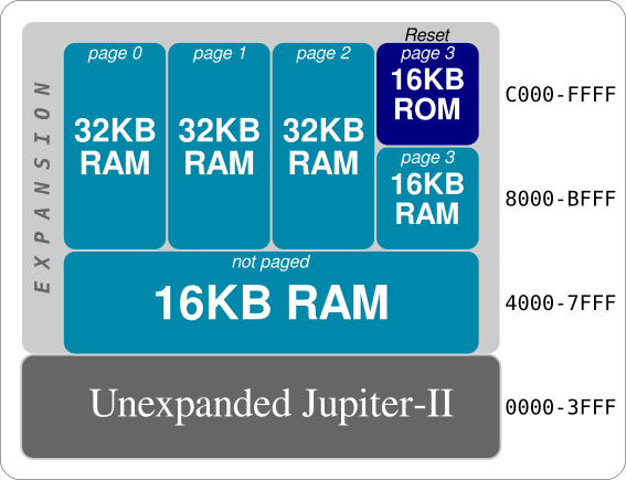
Note: System resets to page 3
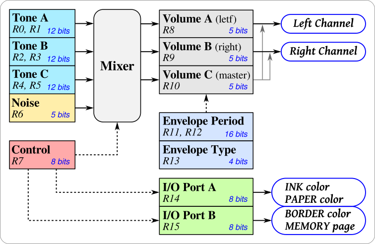
   bits: 76543210 76543210
  R1 R0: ----tttt tttttttt : Tone generator A period (12-bits) 0-4095
  R3 R2: ----tttt tttttttt : Tone generator B period (12-bits) 0-4095
  R5 R4: ----tttt tttttttt : Tone generator C period (12-bits) 0-4095
     R6:          ---ttttt : Noise generator period  (5-bits)  0-31
     R7:          ppcbaCBA : I/O port and sound channel enablers
     R8:          ---Mvvvv : Channel A Volume (v) and Envelope Mode (M)
     R9:          ---Mvvvv : Channel B Volume (v) and Envelope Mode (M)
    R10:          ---Mvvvv : Channel C Volume (v) and Envelope Mode (M)
R12 R11: tttttttt tttttttt : Envelope period (16-bits) 0-65535
    R13:          ----calh : Envelope Shape: Continue (c), Attack (a), Alternate(l), Hold (h)
    R14:          dddddddd : I/O Port-A data
R15: dddddddd : I/O Port-B dataR0..R6: Tone and Noise Period (Frequency) settings
t = 203125 / f , where f is the desirable frequency in Hz
Tone Range: 49.6 Hz to 203.1 kHz (0..4095)
Noise Range: 6.55 kHz to 293.1 kHz (0..31)
R7: Tone and Noise Mixer and I/O Ports direction
R8..R10: Channel volume
R11, R12: Envelope period
t = s / 78.769e-6 , where s is the desirable period in seconds
Period range: 78.8 us to 5.16 seconds
R13: Envelope Shape combination
R14, R15: Digital I/O Port data
| Qty | Value | Footprint | References |
|---|---|---|---|
| 14 | 2k2 | Resistor_SMD:R_0805_2012Metric_Pad1.15x1.40mm_HandSolder | R16, R21, R26, R27, R28, R29, R38, R39, R43, R44, R45, R46, R48, R57 |
| 12 | 1k2 | Resistor_SMD:R_0805_2012Metric_Pad1.15x1.40mm_HandSolder | R30, R31, R32, R33, R34, R35, R36, R37, R49, R50, R51, R52 |
| 8 | 100n | Capacitor_THT:C_Rect_L7.0mm_W2.5mm_P5.00mm | C7, C8, C9, C10, C11, C12, C13, C14 |
| 8 | 4k7 | Resistor_SMD:R_0805_2012Metric_Pad1.15x1.40mm_HandSolder | R1, R2, R3, R4, R55, R56, R58, R59 |
| 6 | 10k | Resistor_SMD:R_0805_2012Metric_Pad1.15x1.40mm_HandSolder | R7, R9, R10, R12, R53, R54 |
| 6 | 1k | Resistor_SMD:R_0805_2012Metric_Pad1.15x1.40mm_HandSolder | R11, R14, R15, R20, R25, R47 |
| 6 | 3k3 | Resistor_SMD:R_0805_2012Metric_Pad1.15x1.40mm_HandSolder | R17, R18, R22, R23, R40, R41 |
| 4 | MountingHole | Mounting_Holes:MountingHole_3.2mm_M3 | H1, H2, H3, H4 |
| 3 | 75 | Resistor_SMD:R_0805_2012Metric_Pad1.15x1.40mm_HandSolder | R19, R24, R42 |
| 3 | BC817 | Package_TO_SOT_SMD:SOT-23 | Q1, Q2, Q3 |
| 2 | 10u | Capacitor_Tantalum_SMD:CP_EIA-6032-15_Kemet-U_Pad2.25x2.35mm_HandSolder | C3, C6 |
| 2 | 1N914 | Diode_THT:D_DO-35_SOD27_P7.62mm_Horizontal | D1, D2 |
| 2 | 33p | Capacitor_SMD:C_0805_2012Metric_Pad1.15x1.40mm_HandSolder | C4, C5 |
| 2 | 470 | Resistor_SMD:R_0805_2012Metric_Pad1.15x1.40mm_HandSolder | R8, R13 |
| 2 | 74LS257 | Package_DIP:DIP-16_W7.62mm | U7, U9 |
| 1 | 16C450 | Package_DIP:DIP-40_W15.24mm_Socket | U5 |
| 1 | 1M | Resistor_SMD:R_0805_2012Metric_Pad1.15x1.40mm_HandSolder | R6 |
| 1 | 1k5 | Resistor_SMD:R_0805_2012Metric_Pad1.15x1.40mm_HandSolder | R5 |
| 1 | 22p | Capacitor_SMD:C_0805_2012Metric_Pad1.15x1.40mm_HandSolder | C2 |
| 1 | 27C128 | Package_DIP:DIP-28_W15.24mm | U2 |
| 1 | 3.6864 MHz | Crystal:Crystal_HC18-U_Vertical | Y1 |
| 1 | 47p | Capacitor_SMD:C_0805_2012Metric_Pad1.15x1.40mm_HandSolder | C1 |
| 1 | 6116 | Package_DIP:DIP-24_W15.24mm | U6 |
| 1 | 628128 | Package_DIP:DIP-32_W15.24mm | U3 |
| 1 | 74LS574 | Package_DIP:DIP-20_W7.62mm | U8 |
| 1 | AY-3-8910 | Package_DIP:DIP-40_W15.24mm_Socket | U4 |
| 1 | CXO_DIP14 3.6864 MHz | Oscillator:Oscillator_DIP-14 | X1 |
| 1 | Conn_01x03 | Connector_Molex:Molex_KK-254_AE-6410-03A_1x03_P2.54mm_Vertical | J4 |
| 1 | Conn_01x07 | Connector_Molex:Molex_KK-254_AE-6410-07A_1x07_P2.54mm_Vertical | J6 |
| 1 | Conn_01x10 | Connector_Molex:Molex_KK-254_AE-6410-10A_1x10_P2.54mm_Vertical | J3 |
| 1 | Conn_02x15_Odd_Even | Connector_PinHeader_2.54mm:PinHeader_2x15_P2.54mm_Vertical | J7 |
| 1 | Conn_02x25_Odd_Even | Connector_PinHeader_2.54mm:PinHeader_2x25_P2.54mm_Vertical | J1 |
| 1 | Conn_02x25_Odd_Even | Connector_PinSocket_2.54mm:PinSocket_2x25_P2.54mm_Vertical | J2 |
| 1 | GAL22V10 | Package_DIP:DIP-24_W7.62mm_Socket | U1 |


alvaroalea/QL_CST_FLoppyController
A clone of the CST's Floppy Disk Interface for Sinclair QL (PCB version 3 & 4)

It measures 164.5 × 71.8 mm and has 2 copper layers, 1.6 mm thick.
99 parts, built around the 27C128-15, 74LS257PC, 74LS574N and BC817. The full list of its parts is on this page, with links to each part's symbol and footprint where PCBKit's library has them.
From the ricaflops/Jupiter-II-Expansion repository on GitHub, at the commit this page was made from: the board is Jupiter-II_expansion.kicad_pcb. PCBKit opens the board in the browser, with nothing to install.
Its repository publishes it under the MIT licence: you may reuse it on that licence's terms (keep the author's notice, and for a copyleft licence share your changes alike).