
2 layers80 × 60 mm
EnvMonitor
kennySzhucheng/EnvMonitor
🌡️ 智能环境监测站 | STM32F103C8T6 + FreeRTOS + ESP8266 | 温湿度/光照/测距/OLED菜单/ThingSpeak上云 | 从裸机到RTOS到KiCad PCB全流程
27 parts10

 Rando1f/Blink1
a partner in crime, helping you with
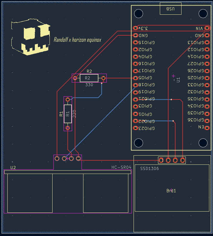
PCB BLINK is an open-source printed circuit board by Rando1f, from the Rando1f/Blink repository on GitHub, published under the MIT licence. It is a 2-layer board of 74.9 × 82.6 mm with 6 parts on 31 nets, routed with 41 tracks and 5 vias.
It is built around the HC-SR04. Its parts include 2 resistors and 2 ICs.
Blink is a desk tracking device that tracks the user's time spent on the desk per session, displaying different animations based on how long the user has been going for. It uses an ultrasonic sensor that measures the distance between the user and itself. If that distance was lower than 15 in., it tracks that the user has been sitting on his desk. If it is more than 15 in., it tracks that the user is away from his desk. the animation are vresions of the same mascot "rando1f"

multiple applications were used in the creatino of blink starting with
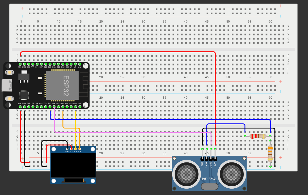
Blink's code is meant to be flashed into an ESP32. This could be done through buying the PCP that was published in production here through the Gerber files, or through using a breadboard with the following wiring.This is going to be done through VS Code and PlatformIO or Arduino IDE, although I recommend using Visual Studio Code because it offers an easier time debugging or adding features if you want to.
blink is plugged into the users device through a micro-usb port that has clearance of about 0.5 mm in the case and is mounted on the bottom of your desk after you screw the lid with body of the case either through superglue or a doubled face tape since blink is fairly light.
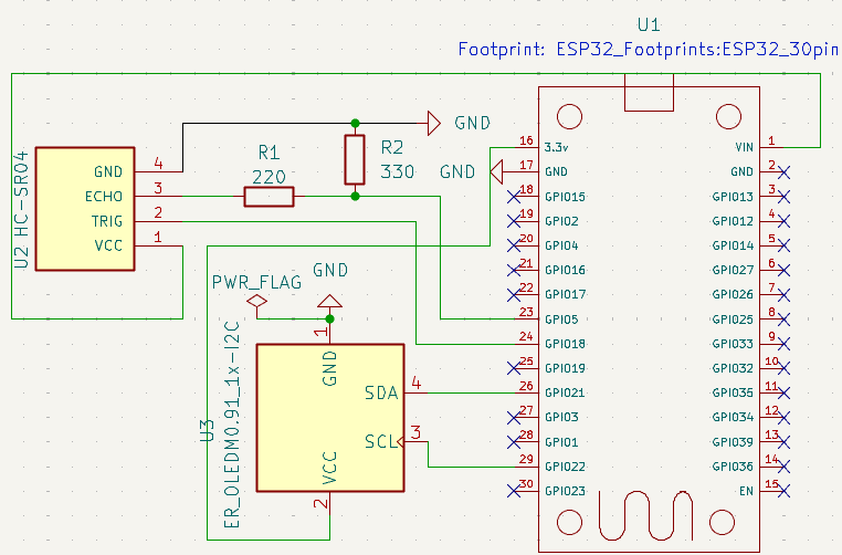
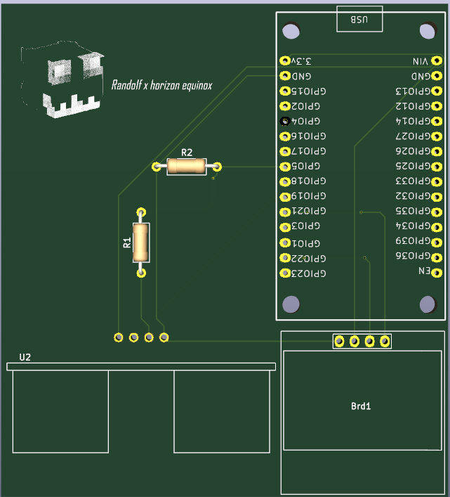
BLINK PCB is built on the wiring showcased in the How to use BLINK section, where it links all of the components to an NGND with an OLED screen having a 3.3 V input with normal I2C protocol wiring, which is SDA: pin 21 and SCL: pin 22.
on the other hand HC-SR04 Has a VIN or a 5V input, and due to the ESP32's 3.3V capacity, a voltage divider of two resistors: Resistor 1 being 220, Resistor 2 being 330, To bring the voltage down towards the 3V, so it doesn't fry or break the ESP32 with default wiring of trig: pin 5 and echo: pin 18.
the esp32 used in this project was esp32 devkit 30pin.
the dimensions of the pcb are: 74.93x85.55x20
 . |  |
the case was done with rough parts mesurments (beside the pcb with a 0.2mm tolarnce) and a casse thickness of 10mm. the case features an ultrasonic sensor opening and an oled screen display cut extrusion where the oled screen would lie on a 90 degree angle with it being connecetd to the pcb trough jumper wires. there are 4 studs on the 4 corners on the inside of the case to have a 3mm clearance below for all of the conections. the case dimensions: 95.13mm x105.75mm x35 mm the oled display dimensions: 20 mm* 27 mm hc-sro4 diameter: 20
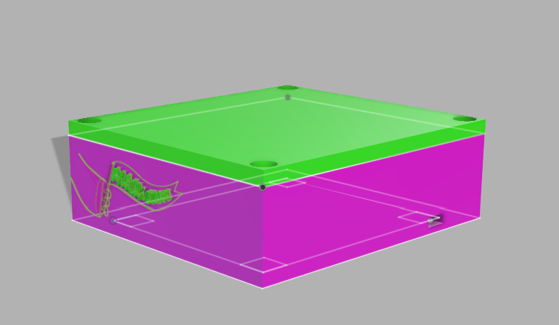
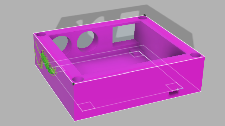
AI was only used for research purposes, and it wasn't used excessively. Rather, it was used as a resource-gathering tool so I could understand more of the project. The read.me is fully human-written, as well as the journal and the bill of materials.
| Qty | Value | Footprint | References |
|---|---|---|---|
| 1 | 220 | Resistor_THT:R_Axial_DIN0207_L6.3mm_D2.5mm_P10.16mm_Horizontal | R1 |
| 1 | 330 | Resistor_THT:R_Axial_DIN0207_L6.3mm_D2.5mm_P10.16mm_Horizontal | R2 |
| 1 | HC-SR04 | HC-SRO4:XCVR_HC-SR04 | U2 |
| 1 | LOGO | LOGO | G*** |
| 1 | SSD1306 | SSD1306:128x64OLED | Brd1 |
| 1 | ~ | ESP32_Footprints:ESP32_30pin | U1 |
It measures 74.9 × 82.6 mm and has 2 copper layers, 1.6 mm thick.
6 parts, built around the HC-SR04. The full list of its parts is on this page, with links to each part's symbol and footprint where PCBKit's library has them.
From the Rando1f/Blink repository on GitHub, at the commit this page was made from: the board is PCB/PCB BLINK.kicad_pcb and its schematic PCB/PCB BLINK.kicad_sch. PCBKit opens the board in the browser, with nothing to install.
Its repository publishes it under the MIT licence: you may reuse it on that licence's terms (keep the author's notice, and for a copyleft licence share your changes alike).
kennySzhucheng/EnvMonitor
🌡️ 智能环境监测站 | STM32F103C8T6 + FreeRTOS + ESP8266 | 温湿度/光照/测距/OLED菜单/ThingSpeak上云 | 从裸机到RTOS到KiCad PCB全流程


NikolaiRadke/Noko_2
The do-it-yourself Arduino-based Noko monster. Version 2 with PCB and 3D printed casing.

billtsol/Maze
This project demonstrates how to use an Arduino board, IR sensors, and a motor driver shield to create a maze-solving robot.

c-lydia/ESP-ROS2
A tiny robot with IMU (MPU5060) and an ultrasonic sensor (HC-SR04), running on micro-ROS, communicating over UDP.

dbrgn/crazyflie2-hcsr04
Ultrasonic sensor (HC-SR04) extension board for the Crazyflie 2.0

YousefAliAicha/aegis-embedded-system
Networked rotating ultrasonic radar system built on the Deneyap Kart 1A (ESP32-S3), with a real-time web dashboard served directly from the board.

YousefAliAicha/sentinel-arduino-firmware
Adaptive traffic-light FSM on the Arduino UNO R3 — pedestrian preemption, LDR-gated night mode with HC-SR04 vehicle detection, and a multiplexed 7-segment countdown. Fully non-blocking.